2.1. 4WD Loader Tutorial (ProcessNet General)
2.1.1. Getting Started
2.1.1.1. Objective
In this tutorial, you will announce how to use ProcessNet by using Microsoft Visual Studio. This tutorial will skip to explain the tutorial model used in this tutorial after because we assume that you have processed the tutorial for ProcessNet. The four processes are:
Use ProcessNet in Microsoft Visual Studio.
Automate the creation of a series of contacts.
Create a custom dialog box that provides user control of the contact.
Automatically check the contact force outputs and only plot the contact forces that have a non-zero output.
2.1.1.2. Audience
This tutorial is intended for intermediate users of RecurDyn who previously learned how to create geometry, joints, and force entities. All new tasks are explained carefully.
2.1.1.3. Procedures
The tutorial is comprised of the following procedures. The estimated time to complete each procedure is shown in the table.
Procedures |
Time (minutes) |
Opening model and Initializing ProcessNet |
10 |
Automating Contact Definition |
35 |
Adding a Dialog Box and Message Output |
20 |
Automating Plot Creation |
20 |
Total |
85 |
2.1.1.4. Estimated Time to Complete
85 minutes
2.1.2. Opening the Model and Initializing ProcessNet
2.1.2.1. Task Objective
Learn how to open a mechanical model in preparation for using ProcessNet and learn how to use ProcessNet in Visual Studio.
2.1.2.2. Estimated Time to Complete
10 minutes
2.1.2.3. Starting RecurDyn
To start RecurDyn and open the initial model:
On your Desktop, double-click the RecurDyn icon. When the Start RecurDyn dialog box appears, close this because you will not be creating a new model but using an existing one.
From the Quick Access Toolbar, click the Open tool.
- Select the file 4WD_Loader_Start.rdyn.(The file path: <InstallDir>\Help\Tutorial\ProcessNet\General\4WDLoader).
Click Open.
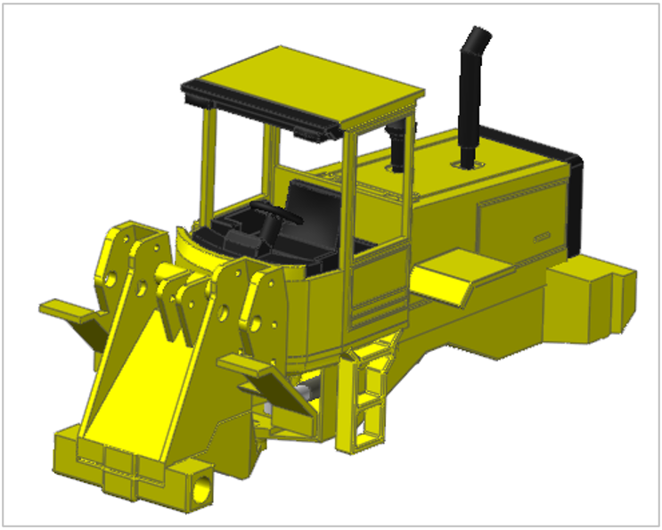
Your model should look like the following.
The red lines are the hydraulic hoses that you will study.
Tip
Note that this view is shown in the (Render Each Object) viewing mode so that you can see past the components on the bottom of the vehicle that might obscure your view of the hoses. If you have difficulty seeing the hoses, you may want to check if you are in the Shaded viewing mode. If so, change back to the Render Each Object viewing mode.
2.1.2.3.1. To save the initial model:
From the File menu, click the Save As function.
Save the model different directory, because you cannot simulation in tutorial directory.
2.1.2.4. Starting ProcessNet
2.1.2.4.1. To start ProcessNet:
ProcessNet General does not provide the Integrated Development Environment (IDE). So, an IDE program needs to use it. If you don’t have the program, we recommend using Visual Studio Expression version supported from Microsoft.
Execute the Visual Studio program.
Visual Studio 2015 Expression version is used in this tutorial.
It is not necessary that RecurDyn is Initializing ProcessNet performed in ProcessNet VSTA.
From the File menu, select New, select Project.
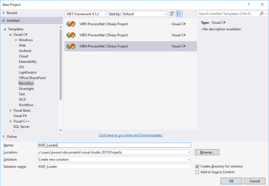
When the New Project dialog window appears, select the Template that corresponds to your version of RecurDyn.
Note
You must use the ProcessNet project that is compatible with your version of RecurDyn. If the version is incorrect, then ProcessNet may not execute properly. The New Project dialog window shows all the templates that are compatible with the installed version of RecurDyn.
If the ProcessNet Template is shown as the above figure, continue to Step 4 below.
If the contents of the window are different, it may be because installation for the Template does not process normally. If so, execute the Visual Studio again after the following process.
Make a copy of the <RecurDyn Version> ProcessNet CSharp Project.zip file in <InstallDir>\Bin\Addin\ProcessNetManager directory and place it in C:\Users\<User Name>\Documents\Visual Studio 2015\Templates\ProjectTemplates directory.
Return to the Visual Studio application.
Repeat Step 2.
Select Templates->Visual C#->RecurDyn. And then, click the <RecurDyn Version> ProcessNet CSharp Project icon.
4D_Loader Project will be created with setting Name, Location, and Solution name as shown in the above figure.
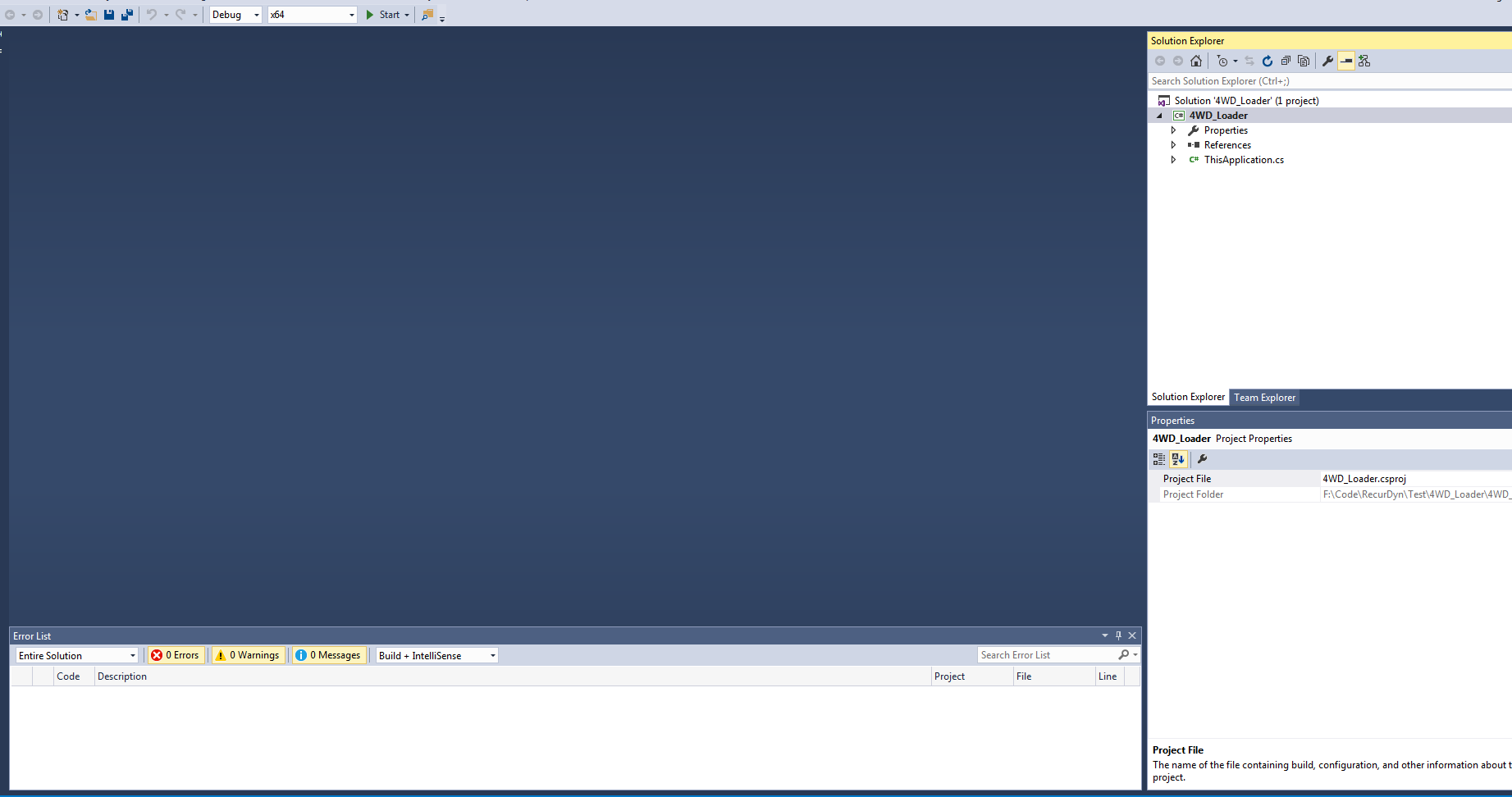
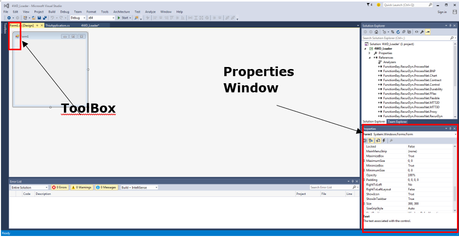
It contains four areas that let you:
Project Editor Window – Write and edit code and design interface objects.
Project Explorer – Get an organized view of your project and its files.
Properties window – View and edit the properties of objects you selected in the Project Editor window or Project Explorer
Message window – View information that is generated as you build and run your code, such as errors in your code.
You are now ready to start developing your first ProcessNet application.
2.1.3. Automating Contact Definition
2.1.3.1. Task Objective
In two steps, you will create a ProcessNet application that creates a set of contacts between the segments of the hoses. You will learn how to:
Obtain the necessary information to create a RecurDyn entity.
Use the ProcessNet help in RecurDyn.
Work in the IDE to develop an application.
You will then run a simulation, view the results, update your application, and rerun the simulation to observe the improved results.
2.1.3.2. Estimated Time to Complete
35 minutes
2.1.3.3. Understanding the Contacts to be Created
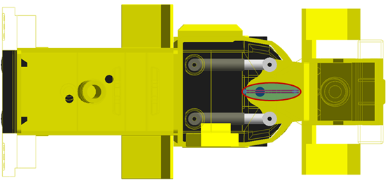
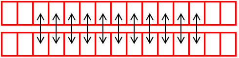
Chapter 1 explained that each of the two hoses have 50 segments, as shown in the figure below. The hoses are separated at the mounting locations at each end. The centerline of the vehicle runs between the hoses. When articulation occurs one hose tends to be stretched more and the other hose stretched less. With the curving of both hoses being different, they can make contact in the middle of the span of the hose.

For your first ProcessNet application, you will create 11 contacts in the middle of the span of the hoses as shown in the figure below.
2.1.3.4. Creating the Base Application
You will now develop the application to create the hose contacts.
2.1.3.4.1. To create the base application:
In the Project Explorer window, double-click the file ThisApplication.cs to open it. The content of the file appears in the Project editor window.
Copy the following code, and insert it after the HelloProcessNet() macro, as shown below.
public void ProcessNetTutorialCreateSolidContact()
{
}
You have now created a stub for your macro. If you were to compile your code now, the method would show up in the list of available macros to run in RecurDyn, although it would not do anything.
Next, insert the following variable declarations into the macro stub you just created (below the opening curly brace, and above the closing curly brace):
public void ProcessNetTutorialCreateSolidContact()
{
    int BodyNumStart = 20;   // Start creating contacts with body 20
    int BodyNumEnd = 30;     // Continue until body 30
    int BodyInterval = 51;   // Interval between body number on hose 1
                             // and corresponding body's number on
                             // hose 2 is 51
}
Note that each variable is followed by an explanation, preceded with two forwards slashes, //. In C#, any characters after these two slashes are ignored by the compiler and can be used as comments in the code, for documentation purposes.
Note
Comments in C# can be preceded by two slashes, //.
After the variable declarations you just added, add the following for loop:
public void ProcessNetTutorialCreateSolidContact()
{
    int BodyNumStart = 20;  // Start creating contacts with body 20
    int BodyNumEnd = 30;    // Continue until body 30
    int BodyInterval = 51;  // Interval between body number on hose 1
                            // and corresponding body's number on
                            // hose 2 is 51

    for (int i = BodyNumStart; i <= BodyNumEnd; i++)
    {
    }
}
The code placed inside the for loop will repeat. For the first loop, the index i will be equal to BodyNumStart. Then i will be incremented by 1, and the next loop will execute. This will repeat while the condition i ≤ BodyNumEnd is true.
Note that i is declared within the for loop statement, meaning that it will be valid only for code within the for loop.
Also note that, in C#, the syntax i++ means to increment i by 1, or i = i + 1, after it has been used in the loop.
Within the for loop you just added, insert the following code:
public void ProcessNetTutorialCreateSolidContact()
{
    int BodyNumStart = 20;  // Start creating contacts with body 20
    int BodyNumEnd = 30;    // Continue until body 30
    int BodyInterval = 51;  // Interval between body number on hose 1
                            // and corresponding body's number on
                            // hose 2 is 51

    for (int i = BodyNumStart; i <= BodyNumEnd; i++)
    {
        int j = i + BodyInterval;  // j is the index for the
                                   // corresponding bodies on hose #2
                                   // Do the contact for corresponding bodies

        IBody baseBody = model.GetEntity("BeamBody" + i.ToString()) as IBody;
        IGeometry baseGeom = baseBody.GetEntity("HollowCircularBeam1") as IGeometry;
        IBody actionBody = model.GetEntity("BeamBody" + j.ToString()) as IBody;
        IGeometry actionGeom= actionBody.GetEntity("HollowCircularBeam1") as IGeometry;
        IContactSolidContact solidContact= model.CreateContactSolidContact("solidContact" + i.ToString(), baseGeom, actionGeom);
    }
}
An explanation of this code block is as follows:
int j = i + BodyInterval;  // j is the index for the
                           // corresponding bodies on hose #2
In the code above:
i is the index for the bodies in hose 1, and j is the index for the bodies in hose 2.
To make sure that the bodies correspond, the value of j will always be equal to i + bodyInterval.
Also, note that j is being declared inside the for loop, and therefore will not be valid outside the for loop.
IBody baseBody = model.GetEntity("BeamBody" + i.ToString()) as IBody;
The code above retrieves the body that we want to use as the base body by its name:
The + character is used to join two strings.
The ToString() method is used to convert the integer value of i to a string.
Therefore, the GetEntity() method looks for bodies by the names “BeamBody20”, “BeamBody21”, etc.
Because the GetEntity() method can return any generic entity, the call must be explicitly casted as IBody to tell the compiler what type to return.
IGeometry baseGeom = baseBody.GetEntity("HollowCircularBeam1") as IGeometry;
The above code retrieves geometry of the base body by its name, HollowCircularBeam1. This geometry will be used to create the solid contact.
The previous two steps are repeated for the action body.
IContactSolidContact solidContact = model.CreateContactSolidContact("solidContact" + i.ToString(), baseGeom, actionGeom);
Finally, the command above creates the solid contact, naming it “solidContact20” (or “solidContact21”, “solidContact22”, etc.). The command uses the base and action geometry we defined in the previous steps.
2.1.3.5. Coding Using IntelliSense
Up to this point, you may have been cutting and pasting code directly from this tutorial. Once you start writing your own macros, however, you will be manually typing in code. A feature of the Visual Studio which helps you code faster is called IntelliSense, and you will now explore how to take advantage of this while also accomplishing the following task.
If compiled, the macro should now create a contact with the default properties. But the default stiffness and damping values for the Solid Contact are too high. You will now set these contact parameters to lower values.
2.1.3.5.1. To modify the contact parameters using IntelliSense:
After the last line of code, you entered in the previous steps, begin typing the character s. You should see a popup list display as shown below:
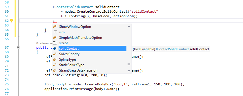
The list contains all of the valid things you could possibly type next, including names of variables accessible at this part of the code, methods you could call, etc.
From the IntelliSense list, locate solidContact.
Select solidContact by double-clicking on it or by pressing Enter.
Next, type the period character (.).
Select ContactProperty from the IntelliSense list.
Continue this procedure until you have typed:
solidContact.ContactProperty.StiffnessCoefficient.Value =1000;
Repeat this procedure to type the next line:
solidContact.ContactProperty.DampingCoefficient.Value = 0.1;
In the end, the method should appear in its entirety as shown below:
public void ProcessNetTutorialCreateSolidContact()
{
    int BodyNumStart = 20;  // Start creating contacts with body 20
    int BodyNumEnd = 30;    // Continue until body 30
    int BodyInterval = 51;  // Interval between body number on hose 1
                            // and corresponding body's number on
                            // hose 2 is 51

    for (int i = BodyNumStart; i <= BodyNumEnd; i++)
    {
        int j = i + BodyInterval;  // j is the index for the
                                   // corresponding bodies on hose #2
                                   //Do the contact for corresponding bodies

        IBody baseBody = model.GetEntity("BeamBody" + i.ToString()) as IBody;
        IGeometry baseGeom = baseBody.GetEntity("HollowCircularBeam1") as IGeometry;
        IBody actionBody = model.GetEntity("BeamBody" + j.ToString()) as IBody;
        IGeometry actionGeom = actionBody.GetEntity("HollowCircularBeam1") as IGeometry;
        IContactSolidContact solidContact = model.CreateContactSolidContact("solidContact"+ i.ToString(), baseGeom, actionGeom);

        solidContact.ContactProperty.StiffnessCoefficient.Value =1000;
        solidContact.ContactProperty.DampingCoefficient.Value = 0.1;
    }
}
There should be no errors or warnings in the Error List window at the bottom of the IDE window.
2.1.3.6. Building and Running the Macro
2.1.3.6.1. To build and run the macro:
If there are any errors or warnings, check the listing and make any corrections.
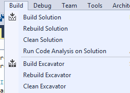
From the Build menu, select Build Solution.
Return to RecurDyn, and from the ProcessNet(General) group in the Customize tab, click the Run function.
Load the DLL file built before in ProcessNet Manager Window.
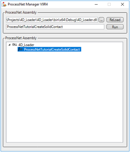
Select ProcessNetTutorialCreateSolidContact from the list of macros. Its name is loaded in the field next to the Run button.
Click Run.
Eleven contacts are added to your model.
2.1.3.7. Running a Simulation
You are now ready to run a simulation.
2.1.3.7.1. To run a simulation:
From the Simulation Type group in the Analysis tab, click the Dynamic / Kinematic Analysis function.
Set the simulation to run for 2.0 seconds with 300 steps and a Plot Multiplier Step Factor of 5 as shown in the figure on the below.
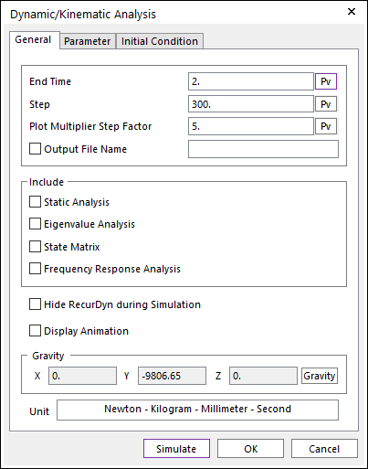
Click Simulate. The simulation will run in 3-4 minutes, depending on the speed of your computer.
2.1.3.8. Viewing the Results
2.1.3.8.1. To view the results:
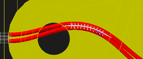
Set up the model so you are looking at a bottom view of the vehicle with the Render Each shading mode turned on.
In the Simulation Toolbar, click the Play tool.
At the end of the simulation the hoses are deformed as shown in the figure to the below.
Turn on the action force display of all of the contacts by:
Selecting the first Solid contact in the Database Window.
While holding down the Shift key, select the last Solid contact in the Database Window.
Click the right mouse button and select Properties.
In the dialog box that appears, click on the Solid page. At the bottom of the dialog box use the pulldown menu to set the Force Display to Action.
Click OK.
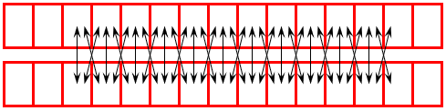
Play the animation again and you will see that the forces are slightly erratic.
As you watch the motion you can see that the hoses slide with respect to each other. It may not be enough to have contact between corresponding segments. Contact with neighboring segments may also be required. This is shown in the figure below.
2.1.3.9. Adding Additional Contacts
2.1.3.9.1. To add additional contacts:
Make the following code changes.
        IContactSolidContact solidContact = model.CreateContactSolidContact("solidContact" + i.ToString(), baseGeom, actionGeom);
        solidContact.ContactProperty.StiffnessCoefficient.Value = 1000;
        solidContact.ContactProperty.DampingCoefficient.Value = 0.1;

        // Do the contact for body i+1 and body j
        solidContact = model.CreateContactSolidContact("solidContact" + i.ToString() + "a",
        (model.GetEntity("BeamBody" + Convert.ToString(i + 1)) as IBody).
        GetEntity("HollowCircularBeam1") as IGeometry,
        (model.GetEntity("BeamBody" + j.ToString()) as IBody).GetEntity("HollowCircularBeam1")
        as IGeometry);
        solidContact.ContactProperty.StiffnessCoefficient.Value = 1000;
        solidContact.ContactProperty.DampingCoefficient.Value = 0.1;

        // Do the contact for body i and body j+1
        solidContact = model.CreateContactSolidContact("solidContact" + Convert.ToString(i) + "b",
        (model.GetEntity("BeamBody" + i.ToString()) as IBody).GetEntity("HollowCircularBeam1")
        as IGeometry, (model.GetEntity("BeamBody" + Convert.ToString(j + 1))
        as IBody).GetEntity("HollowCircularBeam1") as IGeometry);
        solidContact.ContactProperty.StiffnessCoefficient.Value = 1000;
        solidContact.ContactProperty.DampingCoefficient.Value = 0.1;

    }
}
Here, two more contacts are created for each loop through the code. The contact between the i+1th segment on hose 1 and the j th segment on hose 2 is named with an “a” suffix (i.e. “solidContact20a”). Similarly, the contact between the between the ith segment on hose 1 and the j+1 th segment on hose 2 is named with a “b” suffix (i.e. “solidContact20b”).
Note
Contact creation will not happen if a contact with the same name already exists.
You might notice that the syntax for creating these additional contacts is in a more compact, efficient form. For example, retrieving the action body and geometry are all done within the CreateContactSolidContact() method, whereas earlier separate temporary variables were declared and assigned to store the value of each. This syntax makes it more efficient to code, but you need to make sure that you cast the return object of the methods explicitly with the as clause (i.e. as IBody or as IGeometry).
2.1.3.10. Repeating the Build, Simulation, and Viewing Processes
Repeat the earlier steps to determine the effect on the model from the changes you just made.
2.1.3.10.1. To repeat the processes:
Ensure there are no errors or warnings in the Error List window at the bottom of the IDE window. If there are, check the listing and make any corrections. From the Build menu, select Build Solution.
Return to RecurDyn and delete all of the contacts that were defined for the previous run.
From the ProcessNet(General) group in the Customize tab, click the Run function.
Click Run.
33 contacts are added to your model.
Rerun the simulation with the same parameters as the previous run. With the additional contacts the simulation will run in 4-5 minutes.
Turn on the action force display of all of the contacts using the same procedure that was described earlier.
In the Simulation toolbar, in the animation controls, click Play, again looking at a bottom view of the vehicle with the Render Each shading mode turned on.
You will see that the contact forces are now much smoother.
2.1.4. Adding a Dialog and Message Output
In this chapter, you will create a dialog window that will allow the user to control which segments to create contacts between. This will include designing the layout of the dialog and adding code to the existing subroutine to call the new dialog.
2.1.4.1. Task Objective
Learn how to increase the flexibility of your application by creating a dialog window that will allow the user to control how the hose-to-hose contacts are created. Also, learn how to display a message to the user in the RecurDyn message window.
2.1.4.2. Estimated Time to Complete
20 minutes
2.1.4.3. Designing a Dialog
2.1.4.3.1. To design a new dialog window:
Return to Visual Studio.
From the Project menu, select Add Windows Form.
In the Add New Item dialog box, select Windows Form, as shown below.
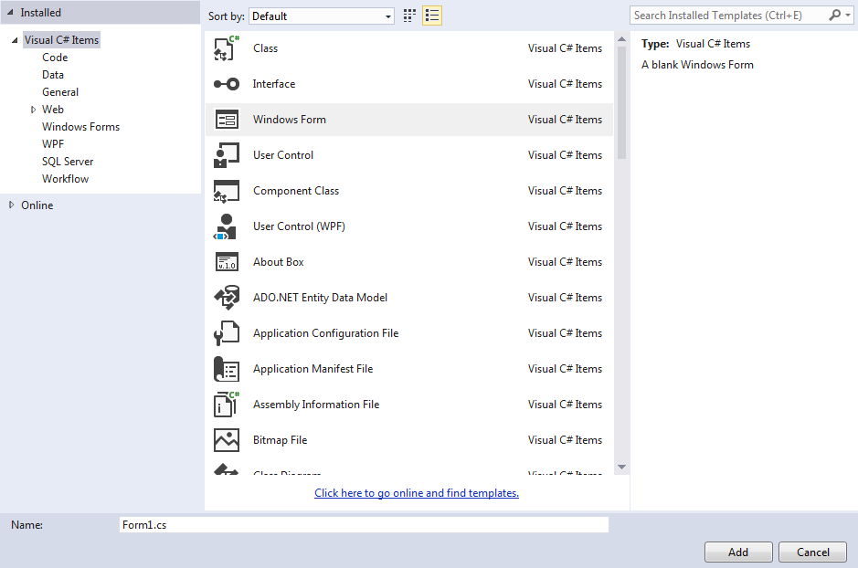
Accept the default name Form1.cs.
Click Add.
The design window for Form1, Form1.cs [Design], appears in the IDE Project Editor window.
In the upper left of the screen, move the cursor over the Toolbox tool.
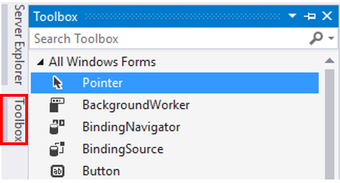
A fly-out menu appears, which contains the different elements you could add to dialog windows and other similar controls.
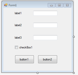
In the Common Controls list, click Label, and drag it into the upper left area of the dialog you are designing.
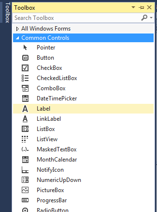
Repeat the same step as above, except drag TextBox into the dialog, to the right of the Label, as shown on the below.
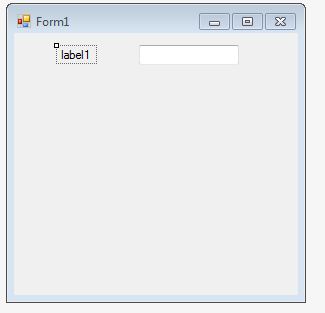
Repeat the last two steps, twice, so there is a total of three rows of labels followed by text boxes.
From the Toolbox, add a Checkbox below the other elements.
From the Toolbox, add two Buttons below the other elements.
At this point, the dialog should appear as shown on the below.
Click label1 to select it.
In the Properties window in the lower right corner, change the value of Text to Starting Segment.
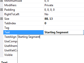
Tip
The edit field for the label is small, but you can edit the name more easily by clicking the dropdown arrow to the right of the field, as shown on the below. You have a larger area to work with.
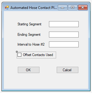
Repeat the last step for Labels 2 and 3, the Checkbox, button1 and button2, and the Dialog, using the following table for the name changes:
Dialog Element
Text
label1
Starting Segment
label2
Ending Segment
label3
Interval to Hose #2
checkBox1
Add Offset Contacts
button1
OK
button2
Cancel
Form1
Automated Hose Contact
Tip
Select the dialog itself by clicking anywhere where there are no components.
Resize and move the dialog elements so the dialog appears as shown at below.
Tip
The Visual Studio provides alignment guides to aid in this step.
From the File menu, select Save All. This will save Form1.cs as well as the project setup.
2.1.4.4. Defining the Behavior of the Dialog
At this point, the appearance of the dialog has been set. You now have to define its behavior, by adding variables that will save the values users input into the textboxes, as well as the state of the checkbox. You will add code that will initialize all these variables and will also define what happens when the user clicks the OK button.
2.1.4.4.1. To define the dialog window behavior:
In the dialog design window, double-click any part of the dialog that is not another component.
This displays the code of Form1.cs in the IDE Project editor window and creates stubs for a subroutine called Form1_Load. This subroutine will be called whenever a new copy of the dialog box is created and loaded, so this is an ideal place to put code that will initialize variables.
Insert the following block of code, which defines the variables that are used in the dialog box:
public partial class Form1 : Form
{
    public int BNumStart;
    public int BNumEnd;
    public int BodyInterval;
    public bool AddOffsetFlag;

    public Form1()
    {
        InitializeComponent();
    }
Insert the following block of code, which sets up the initial values that appear in the dialog box:
private void Form1_Load(object sender, EventArgs e)
{
    textBox1.Text = "20";
    BNumStart = 20;
    textBox2.Text = "30";
    BNumEnd = 30;
    textBox3.Text = "51";
    BodyInterval = 51;
    checkBox1.Checked = false;
}
Return to the dialog design window and double-click on the OK button.
Within the new method that was just automatically created, insert the following code as shown below:
private void button1_Click(object sender, EventArgs e)
{
    BNumStart = Convert.ToInt32(textBox1.Text);
    BNumEnd = Convert.ToInt32(textBox2.Text);
    BodyInterval = Convert.ToInt32(textBox3.Text);
    AddOffsetFlag = checkBox1.Checked;
    DialogResult = DialogResult.OK;
    Close();
}
Return to the dialog design window again and this time double-click on the Cancel button.
Within the new method that was just automatically created, insert the following code as shown below:
private void button2_Click(object sender, EventArgs e)
{
    Close();
}
From the File menu, select Save Form1.cs.
2.1.4.5. Displaying the Dialog when Running the Macro
Now you will define when the dialog is displayed when running the macro, by creating a new instance of it within the macro subroutine.
2.1.4.5.1. To display the dialog window from within the macro:
Copy the entire ProcessNetTutorialCreateSolidContact subroutine that you just created.
Paste it into ThisApplication.cs, renaming the sub ProcessNetTutorialCreateSolidContact_WithDialog.
Make the following changes to the subroutine, as indicated below (delete the code indicated with strikethroughs). An explanation of each change will follow.
public void ProcessNetTutorialCreateSolidContact_WithDialog()
{
    i̶n̶t̶ ̶B̶o̶d̶y̶N̶u̶m̶S̶t̶a̶r̶t̶ ̶=̶ ̶2̶0̶;̶ ̶ ̶/̶/̶ ̶S̶t̶a̶r̶t̶ ̶c̶r̶e̶a̶t̶i̶n̶g̶ ̶c̶o̶n̶t̶a̶c̶t̶s̶ ̶w̶i̶t̶h̶ ̶b̶o̶d̶y̶ ̶2̶0̶
    ̶i̶n̶t̶ ̶B̶o̶d̶y̶N̶u̶m̶E̶n̶d̶ ̶=̶ ̶3̶0̶;̶ ̶ ̶ ̶ ̶/̶/̶ ̶C̶o̶n̶t̶i̶n̶u̶e̶ ̶u̶n̶t̶i̶l̶ ̶b̶o̶d̶y̶ ̶3̶0̶
    ̶i̶n̶t̶ ̶B̶o̶d̶y̶I̶n̶t̶e̶r̶v̶a̶l̶ ̶=̶ ̶5̶1̶;̶ ̶ ̶/̶/̶ ̶I̶n̶t̶e̶r̶v̶a̶l̶ ̶b̶e̶t̶w̶e̶e̶n̶ ̶b̶o̶d̶y̶ ̶n̶u̶m̶b̶e̶r̶ ̶o̶n̶ ̶h̶o̶s̶e̶ ̶1̶
                            ̶/̶/̶ ̶a̶n̶d̶ ̶c̶o̶r̶r̶e̶s̶p̶o̶n̶d̶i̶n̶g̶ ̶b̶o̶d̶y̶'̶s̶ ̶n̶u̶m̶b̶e̶r̶ ̶o̶n̶
                            ̶/̶/̶ ̶h̶o̶s̶e̶ ̶2̶ ̶i̶s̶ ̶5̶1̶

    // Create a Form
    Form1 MyForm = new Form1();

    // Open the Dialog
    MyForm.ShowDialog();

    if (MyForm.DialogResult == System.Windows.Forms.DialogResult.OK)
    {
        int NumContacts = 0;
        int BodyNumStart = MyForm.BNumStart;
        int BodyNumEnd = MyForm.BNumEnd;
        int BodyInterval = MyForm.BodyInterval;

        for (int i = BodyNumStart; i <= BodyNumEnd; i++)
        {
            int j = i + BodyInterval;  // j is the index for the
                                       // corresponding bodies on
                                       // hose #2
                                       // Do the contact for corresponding bodies
            .
            .
            .
            solidContact.ContactProperty.DampingCoefficient.Value = 0.1;

            // Increment the number of contacts
            NumContacts = NumContacts + 1;

            if (MyForm.AddOffsetFlag)
            {
                Do the contact for body i+1 and body j
                .
                .
                .
                Do the contact for body i and body j+1
                .
                .
                .
                solidContact.ContactProperty.DampingCoefficient.Value = 0.1;
                // Increment the number of contacts
                NumContacts = NumContacts + 2;
            }
        }
    application.PrintMessage(NumContacts.ToString() + "contacts were created between the two hoses.");
    }
}
Change 1:
int BodyNumStart = 20;   // Start creating contacts with body 20
int BodyNumEnd = 30;     // Continue until body 30
int BodyInterval = 51;   // Interval between body number on hose 1
                         // and corresponding body's number on
                         // hose 2 is 51
Here you deleted code which hard-coded the values which will now be determined by user input into the dialog.
Change 2:
// Create a Form
Form1 MyForm = new Form1();

// Open the Dialog
MyForm.ShowDialog();

if (MyForm.DialogResult == System.Windows.Forms.DialogResult.OK)
{
     int NumContacts = 0;
Here you created a new instance of Form1 and displayed it. The if statement tests for the response of the user. If the user clicks OK, the code enclosed in the if statement is executed. Also, a variable called NumContacts is declared, which keeps track of the number of contacts that have been created. The if statement is closed in Change 5.
Change 3:
int BodyNumStart = MyForm.BNumStart;
int BodyNumEnd = MyForm.BNumEnd;
int BodyInterval = MyForm.BodyInterval;
Here you replaced the code where the segment number variables were hard-coded. The new code assigns these variables with the values the user enters in the dialog.
Change 4:
// Increment the number of contacts
NumContacts = NumContacts + 1;

if (MyForm.AddOffsetFlag)
{
    .
    .
    .
    // Increment the number of contacts
    NumContacts = NumContacts + 2;
NumContacts is updated appropriately. Also, the if statement tests for whether or not the user checked the Add Offset Contacts checkbox. If the user did, the code enclosed by the if statement is executed.
Change 5:
         application.PrintMessage(NumContacts.ToString() + "contacts were created between the two hoses.");
   }
}
An output message is displayed to the user within the RecurDyn message window, which confirms how many contacts were created. Also, the outermost if statement is closed (see Change 1).
From the File menu, select Save ThisApplication.cs.
2.1.4.6. Test the Dialog Box
Repeat the earlier steps to build the macro and test it with the changes you just made.
2.1.4.6.1. To repeat the processes:
Ensure there are no errors or warnings in the Error List window at the bottom of the IDE window. If there are, check the listing and make any corrections. From the Build menu, select Build Solution.
Return to RecurDyn and delete all of the contacts that were defined for the previous run.
From the ProcessNet(General) group in the Customize tab, click the Run function.
You will see that there is a new item in the list, ProcessNetDialogCreateSolidContact_WithDailog. Select that item.
Its name is loaded in the field next to the Run button.
Click Run. The dialog box shown on the below appears.
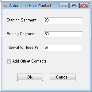
Click OK to use the default values.
You should now see in the Database Window that 11 contacts have been created. A confirmation message in the RecurDyn message output window also states that 11 contacts were created.
Delete the contacts that were just created by clicking on the Undo arrow in RecurDyn, and run the macro again, but this time select the Add Offset Contacts checkbox.
You should see that 33 contacts are added to your model, and again there will be a confirmation message in the RecurDyn message output window.
Restore the results from the simulation that was run earlier. Click on the File menu and select the Import command. Use the pull-down menu to change the file type to RecurDyn Animation Data File (*.rad). Select the file 4WD_Loader.rad and click Open.
Close the ProcessNet Manager window.
2.1.5. Automating Plot Creation
In this chapter, you will make two plots in a multi-window plot:
The first plot will display the force magnitudes of the individual segment-to-segment contacts. Contacts that do not experience any force will be excluded, so the plot contains only data of interest. The first plot will be enhanced with improved formatting, addition of labels, and scaling of the X-axis to focus on the time of hose contact.
The second plot will display the total hose-to-hose contact force, broken into X, Y, and Z components. Both plots will be labeled and formatted.
2.1.5.1. Task Objective
Learn how to use ProcessNet commands to automate plotting. This will include:
Importing a plot data file.
Intelligently determining which data to display.
Processing and then plotting the data on a multi-window plot.
Formatting the chart based on the data.
2.1.5.2. Estimated Time to Complete
20 minutes
2.1.5.3. Creating a Dialog
To determine which data to plot, another dialog window that reads user input will be needed. This dialog will be very similar to the first dialog you created, so start by copying that dialog.
2.1.5.3.1. To create the new dialog window:
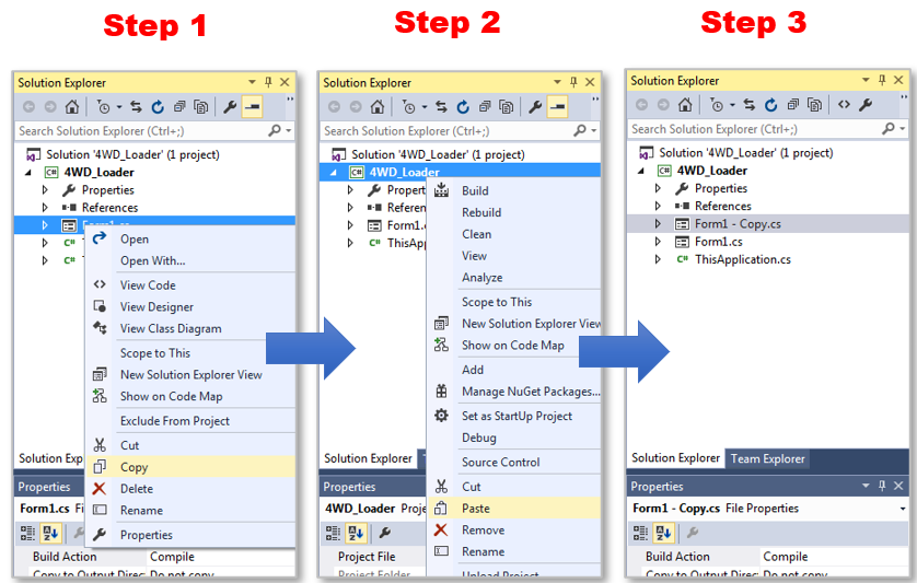
In the Project Explorer window on the right, right-click Form1.cs, and select Copy (refer to the diagram below for the next several steps).
Right-click ProcessNet and select Paste.
Click Copy of Form1.cs to highlight it, and then click again to edit its name.
Change the name to Form2.cs.
2.1.5.3.2. To adjust the new dialog window:
Double-click Form2.cs to open it.
The dialog design window appears.
From the View menu, select Code to display the code window.
In the code, perform a search for Form1. Replace all instances with “Form2”. There should be 3 instances of this, as shown below:
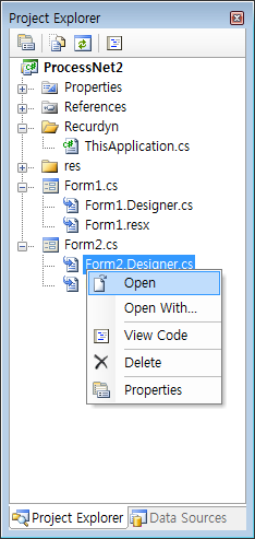
namespace ProcessNet.csproj
{
    public partial class Form1 Form2 : Form
    {
        public int BNumStart;
        public int BNumEnd;
        public int BodyInterval;
        public bool AddOffsetFlag;

        public ̶F̶o̶r̶m̶1̶  Form2()
        {
            InitializeComponent();
        }

        private void ̶F̶o̶r̶m̶1̶_̶L̶o̶a̶d̶  Form2_Load(object sender, EventArgs e)
        {
            textBox1.Text = "20";
            BNumStart = 20;
In the Project Explorer window, right-click on Form2.Designer.cs and select Open, as shown at below.
Again, perform a search for Form1. Replace all instances with Form2. There should be 2 instances of this, as shown below:
partial class Form1 Form2
{
    .
    .
    .
    private void InitializeComponent()
    {
        .
        .
        .
        this.Load += new System.EventHandler(this.̶F̶o̶r̶m̶1̶_̶L̶o̶a̶d̶  Form2_Load);
        this.ResumeLayout(false);
        this.PerformLayout();
    }
Above the IDE Project Editor window, click Form2.cs [Design] tab.
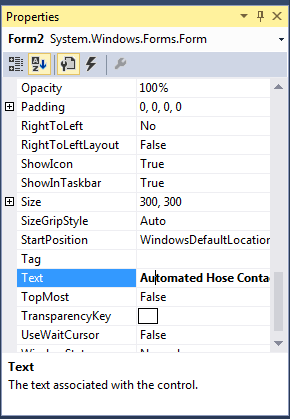
Select the dialog window itself (not any of its individual components), by clicking on any part of the dialog which is not a component.
In the Properties window (lower-right of screen), change the Text to Automated Hose Contact Plotting.
In the IDE Project Editor window, click and drag the right side of the dialog window to resize it so the new title is fully displayed.
Click the Add Offset Contacts label.
In the Properties window, change the text to Offset Contacts Used.
From the File menu, select Save All.
2.1.5.4. Plotting the Contact Forces
You will now create a new subroutine in the ThisApplication class.
2.1.5.4.1. To create a new subroutine:
Copy the following code block (including code on the next page) and insert it into the ThisApplication class. (
Tip
Make sure that this code is inserted within the class but not within another subroutine.)
public void ProcessNetTutorialPlotData()
{
    // Create an auto contact plotting dialog
    Form2 MyForm = new Form2();

    // Open the dialog
    MyForm.ShowDialog();

    // If the user clicked OK:
    if (MyForm.DialogResult == System.Windows.Forms.DialogResult.OK
    {
        // Get the TIME data
        double[] TIME = plotDocument.GetPlotData("4WD_Loader/TIME");

        // |||||||| Plot individual contact forces ||||||||

        // Active upper-left plot window
        plotDocument.ActivateView(0, 0);

        for (int bodyIndex = MyForm.BNumStart; bodyIndex <= MyForm.BNumEnd; bodyIndex++)
        {
            // Load up the contact name number array

            String[] contNum = {bodyIndex.ToString(), "", ""};

            if (MyForm.AddOffsetFlag)
            {
                contNum[1] = bodyIndex.ToString() + "a";
                contNum[2] = bodyIndex.ToString() + "b";
            }

            for (int contNumIndex = 0; contNumIndex < contNum.Length; contNumIndex++)
            {
                if (String.Compare(contNum[contNumIndex], "") != 0)
                {
                    // Get the contact data for this segment
                    double[] contact = plotDocument.GetPlotData("4WD_Loader/Contact/Solid Contact/solidContact" + contNum[contNumIndex] + "/FM_SolidContact");

                    // Plot vs. TIME
                    plotDocument.DrawPlot("Contact" + contNum[contNumIndex], TIME, contact);
                }
            }
        }
    }
}
The first two commands create a new Form2 window and display it to the user:
// Create an auto contact plotting dialog
Form2 MyForm = new Form2();

// Open the dialog
MyForm.ShowDialog();
The following if statement tests whether or not the user clicked the OK button, and executes the enclosed code if the user did:
// If the user clicked OK:
if (MyForm.DialogResult == System.Windows.Forms.DialogResult.OK
The following code obtains the plot data for TIME from the imported file and saves it to a new array.
// Get the TIME data
double[] TIME = plotDocument.GetPlotData("4WD_Loader/TIME");
The following command activates the upper left plotting window:
// Active upper-left plot window
plotDocument.ActivateView(0, 0);
The following code loads up an array of strings which will contain partial names of the data to plot. The array is loaded according to what the user entered into the dialog. For example, if the user set the Starting Contact to 20 and selected the “Offset Contacts Used” checkbox, then during the first loop the array will contain the strings {“20”, “20a”, “20b”}.
for (int bodyIndex = MyForm.BNumStart; bodyIndex <= MyForm.BNumEnd; bodyIndex++)
{
    // Load up the contact name number array

    String[] contNum = {bodyIndex.ToString(), "", ""};

    if (MyForm.AddOffsetFlag)
    {
        contNum[1] = bodyIndex.ToString() + "a";
        contNum[2] = bodyIndex.ToString() + "b";
    }

    for (int contNumIndex = 0; contNumIndex < contNum.Length; contNumIndex++)
    {
        if (String.Compare(contNum[contNumIndex], "") != 0)
        {
This next command retrieves plot data by the name of the data. The name is the same as that seen from the plotting database window, using the “/” character as a separator:
// Get the contact data for this segment
double[] contact = plotDocument.GetPlotData("4WD_Loader/Contact/Solid Contact/solidContact" + contNum[contNumIndex] + "/FM_SolidContact");
Finally, the next command draws the data in the plot window.
// Plot vs. TIME
plotDocument.DrawPlot("Force (N)", TIME, contact);
Save the file.
From the Build menu, select Build Solution.
2.1.5.4.2. To test the edited subroutine with plotting:
Return to the RecurDyn modeling window with the current loader model loaded and open a plotting window.
From the ProcessNet(General) group in the Customize tab, click the Run function.
From the list, select ProcessNetTutorialPlotData.
Select Run.
In the Dialog2 dialog window that appears, accept the default segment numbers, and check Offset Contacts Used.
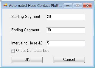
You should see the following plot (as adjusted to the size of your RecurDyn Plot Window):
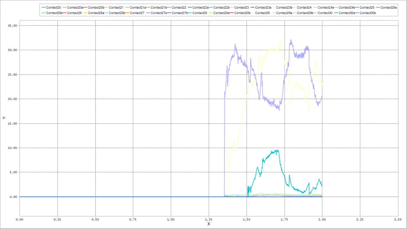
Above, all 33 contacts have been plotted, but only a fraction of the curves contain non-zero values because the contact between the hoses is restricted to several segments on each hose. Also, all the contact occurs at the last third of the simulation, but the plot shows the entire timeline of the simulation.
2.1.5.5. Improving the Contact Force Plot
The plot can be improved so it focuses on the interesting behavior, by:
Only plotting non-zero contacts.
Reducing the timeline (or range of the X-axis) so it only contains non-zero contact behavior.
You will start by only plotting non-zero contacts. Some of the logic for reducing the timeline will be introduced but formatting the X-axis will come later.
2.1.5.5.1. To plot only non-zero contact forces:
Make the following changes to the code:
public void ProcessNetTutorialPlotData()
{
    // Create an auto contact plotting dialog
    Form2 MyForm = new Form2();

    // Open the dialog
    MyForm.ShowDialog();

    // If the user clicked OK:
    if (MyForm.DialogResult == System.Windows.Forms.DialogResult.OK
    {
        // Get the TIME data
        double[] TIME = plotDocument.GetPlotData("4WD_Loader/TIME");

        // Initialize variables for X-axis limits
        double timeAtFirstContact = TIME[TIME.Length - 1];
        double timeAtLastContact = 0;

        // |||||||| Plot individual contact forces ||||||||

        // Active upper-left plot window
        plotDocument.ActivateView(0, 0);

        for (int bodyIndex = MyForm.BNumStart; bodyIndex <= MyForm.BNumEnd; bodyIndex++)
        {
            // Load up the contact name number array
            String[] contNum = {bodyIndex.ToString(), "", ""};

            if (MyForm.AddOffsetFlag)
            {
                contNum[1] = bodyIndex.ToString() + "a";
                contNum[2] = bodyIndex.ToString() + "b";
            }

            for (int contNumIndex = 0; contNumIndex < contNum.Length; contNumIndex++)
            {
                if (String.Compare(contNum[contNumIndex], "") != 0)
                {
                    // Get the contact data for this segment
                    double[] contact = plotDocument.GetPlotData("4WD_Loader/Contact/Solid Contact/solidContact" + contNum[contNumIndex] + "/FM_SolidContact");

                    ̶/̶/̶ ̶P̶l̶o̶t̶ ̶v̶s̶.̶ ̶T̶I̶M̶E̶
                    ̶p̶l̶o̶t̶D̶o̶c̶u̶m̶e̶n̶t̶.̶D̶r̶a̶w̶P̶l̶o̶t̶(̶"̶C̶o̶n̶t̶a̶c̶t̶"̶+̶ ̶c̶o̶n̶t̶N̶u̶m̶[̶c̶o̶n̶t̶N̶u̶m̶I̶n̶d̶e̶x̶]̶,̶ ̶T̶I̶M̶E̶,̶ ̶c̶o̶n̶t̶a̶c̶t̶)̶;̶

                    // Check for non-zero contact data, and determine
                    // time at first contact
                    int j;
                    bool madeContact = false;
                    for (j = 0; j < contact.Length; j++)
                    {
                        if (contact[j] > 0)
                        {
                            madeContact = true;
                            if (TIME[j] < timeAtFirstContact)
                                timeAtFirstContact = TIME[j];
                            break;
                        }
                    }

                // Determine time at last contact
                j = contact.Length - 1;
                while (j > 0)
                {
                    if (contact[j] > 0)
                    {
                        if (TIME[j] > timeAtLastContact)
                           timeAtLastContact = TIME[j];
                        break;
                    }
                    j--;
                }

                // If non-zero contact data found, then plot vs. TIME
                if (madeContact)
                     plotDocument.DrawPlot("Contact" + contNum[contNumIndex], TIME, contact);
            }
         }
     }
 }
The code now contains logic that goes through the data, now in the form of an array, and searches for non-zero values. This code also records the first and last time the contact was non-zero.
Save the file.
From the Build menu, select Build Solution.
2.1.5.5.2. To test the non-zero contact force plot:
Follow the same steps as before to test the new ProcessNet macro in a new Plot Window (open a new Plot Window to begin).
You should see the following plot.
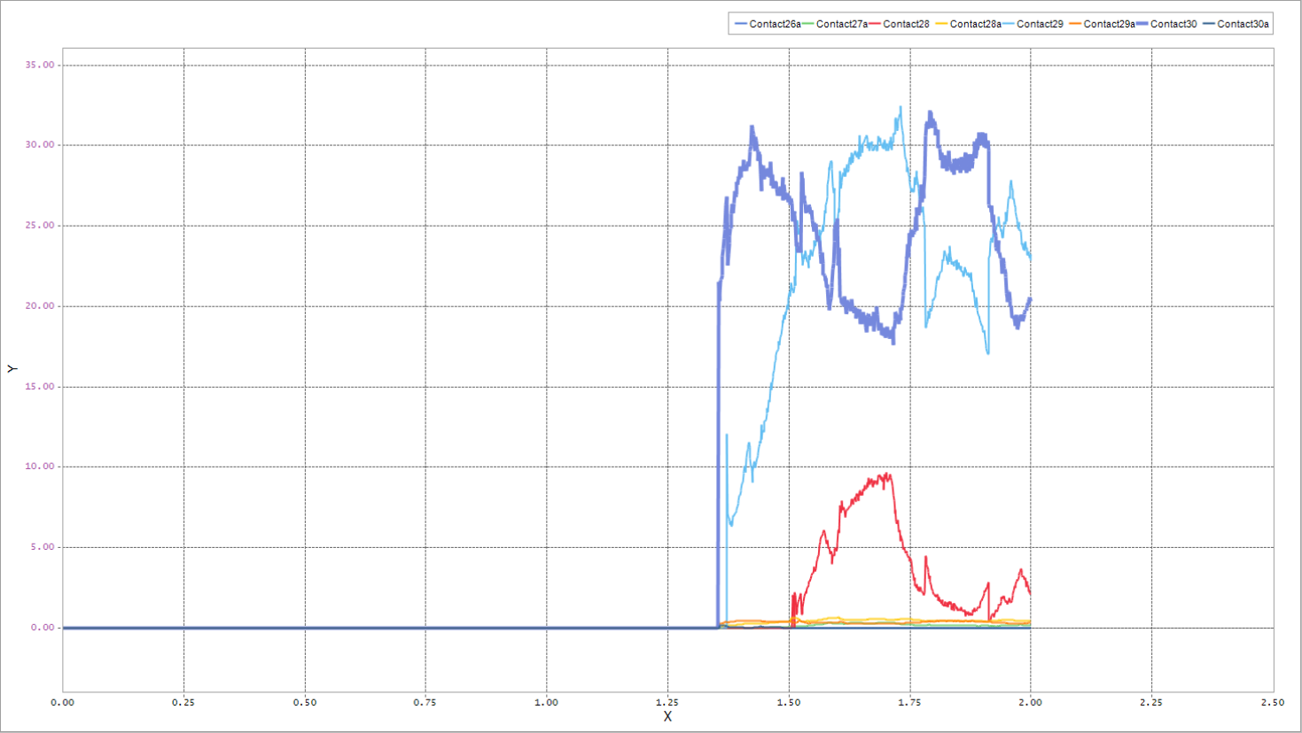
You can now see which contacts are non-zero throughout the simulation. Only 8 of the 33 contacts are non-zero.
2.1.5.6. Improving the Plot Formatting
The last plot completed communicates more clearly than the previous versions, but there is still room for improvement. The plot title and axis labels and titles are not descriptive, and the timescale is still not focused on the interesting part of the simulation. You will now perform some plot formatting using ProcessNet functions.
2.1.5.6.1. To improve the plot formatting:
Make the following code changes:
#region namespace
using System;
using Microsoft.VisualBasic;
using System.Windows.Forms; //IWin32Window
using System.IO;

using FunctionBay.RecurDyn.ProcessNet;
//For C#
using FunctionBay.RecurDyn.ProcessNet.Chart;
//using FunctionBay.RecurDyn.ProcessNet.MTT2D;
//using FunctionBay.RecurDyn.ProcessNet.FFlex;
//using FunctionBay.RecurDyn.ProcessNet.RFlex;
//using FunctionBay.RecurDyn.ProcessNet.Tire;
               // If non-zero contact data found, then plot vs. TIME
               if (madeContact)
               plotDocument.DrawPlot("Contact" + contNum[contNumIndex], TIME, contact);
            }
         }
      }

      // Get Chart object and format

      IChart Chart1 = plotDocument.ActiveChartControl;
      Chart1.Title.Text = "Hose Contact Force";
      Chart1.AxisX.Title.Text = "Time (sec)";
      Chart1.AxisX.Min = 0.1 * Math.Truncate(timeAtFirstContact * 10);
      Chart1.AxisX.Max = 0.1 * Math.Ceiling(timeAtLastContact * 10);
      Chart1.AxisX.LabelsFormat.Decimals = 1;
      Chart1.AxisY.LabelsFormat.Decimals = 1;
      Chart1.AxisY.Title.Text = "Contact Force (N)";
      Chart1.LegendBox.Alignment = LegendBoxAlignment.LegendBoxAlignment_Far;

   }
}
Note that the definition of the X-axis limits Chart1.AxisX.Min and Chart1.AxisX.Max use the variables timeAtFirstContact and timeAtLastContact that were calculated in the earlier section.
Save the file.
From the Build menu, select Build Solution.
2.1.5.6.2. To test the formatting of the plot:
Follow the same steps as before to test the new ProcessNet macro in a new Plot Window (open a new Plot Window to begin).
You should see the following plot:
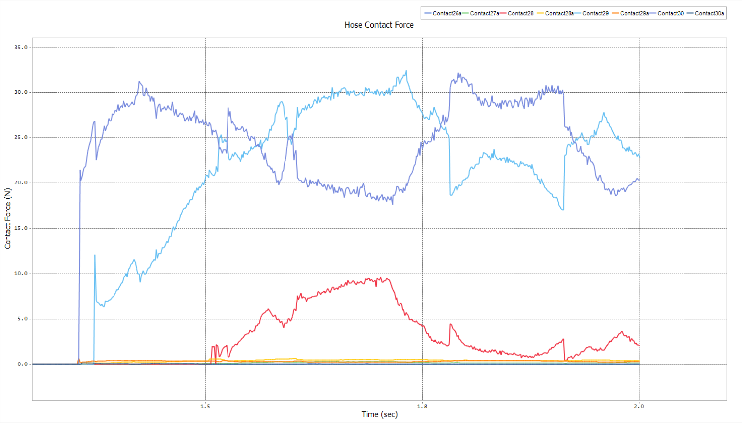
Now the plot has been fully formatted, and the X-axis has been scaled so the non-zero contact can be seen in detail.
2.1.5.7. Plotting the Total X, Y, and Z Contact Force
Suppose that you now want to see what the total contact force between the two hoses is, divided into its X, Y, and Z components. The data for this plot will need to be calculated using the existing data in the plot file. In ProcessNet, because the plot data can be stored in arrays, you can perform mathematical operations on it. For this next plot, you will add array data together to create the sums of the X, Y, and Z components of all the contacts.
Because you have already learned from the previous plot most of the commands to create the new one, a single large block of code will be copied and inserted for this part of the tutorial. Note, however, the additional data processing that sums the arrays together.
2.1.5.7.1. To add the second plot:
Insert the following code block into the location shown below, near the end of the subroutine but within the If statement:
// Get Chart object and format
.
.
.
Chart1.AxisY.Title.Text = "Contact Force (N)";
Chart1.LegendBox.DockedPosition = DockedPositionType.DockedPositionType_Right;

// |||||||| Plot sums of X, Y, and Z components ||||||||

// Activate the lower-left plot window
plotDocument.ActivateView(1, 0);

double[] xSum = new double[TIME.Length];
double[] ySum = new double[TIME.Length];
double[] zSum = new double[TIME.Length];

for (int bodyIndex = MyForm.BNumStart;  bodyIndex <= MyForm.BNumEnd; bodyIndex++)
{
    // Load up the contact name number array

    String[] contNum = {bodyIndex.ToString(), "", ""};
    if (MyForm.AddOffsetFlag)
    {
        contNum[1] = bodyIndex.ToString() + "a";
        contNum[2] = bodyIndex.ToString() + "b";
    }
    for (int contNumIndex = 0; contNumIndex < contNum.Length; contNumIndex++)
    {
        if (String.Compare(contNum[contNumIndex], "") != 0)
        {
            // Get the contact data for this segment
            double[] contactX = plotDocument.GetPlotData("4WD_Loader/Contact/Solid Contact/solidContact" + contNum[contNumIndex] + "/FX_SolidContact");
            double[] contactY = plotDocument.GetPlotData("4WD_Loader/Contact/Solid Contact/solidContact" + contNum[contNumIndex] + "/FY_SolidContact");
            double[] contactZ = plotDocument.GetPlotData("4WD_Loader/Contact/Solid Contact/solidContact" + contNum[contNumIndex] + "/FZ_SolidContact");

            if (contNumIndex == MyForm.BNumStart)
            {
                // If looping through the first contact,
                // initialize the sum arrays
                xSum = contactX;
                ySum = contactY;
                zSum = contactZ;
            }
            else
            {
                // Else, add this contact's array data to the
                // running total
                for (int j = 0; j < TIME.Length; j++)
                {
                    xSum[j] = xSum[j] + contactX[j];
                    ySum[j] = ySum[j] + contactY[j];
                    zSum[j] = zSum[j] + contactZ[j];
                }
            }
        }
    }
}

// Plot vs. TIME
plotDocument.DrawPlot("X Sum", TIME, xSum);
plotDocument.DrawPlot("Y Sum", TIME, ySum);
plotDocument.DrawPlot("Z Sum", TIME, zSum);

// Get Chart object and format
IChart Chart2 = plotDocument.ActiveChartControl;
Chart2.Title.Text = "Total Hose-to-Hose Contact Force";
Chart2.AxisX.Title.Text = "Time (sec)";
Chart2.AxisX.Min = 0.1 * Math.Truncate(timeAtFirstContact * 10);
Chart2.AxisX.Max = 0.1 * Math.Ceiling(timeAtLastContact * 10);
Chart2.AxisX.LabelsFormat.Decimals = 1;
Chart2.AxisY.LabelsFormat.Decimals = 1;
Chart2.AxisY.Title.Text = "Contact Force (N)";
Chart2.LegendBox.Alignment = LegendBoxAlignment.LegendBoxAlignment_Far;
Save the file.
From the Build menu, select Build Solution.
2.1.5.7.2. To test the second plot:
The second plot will be displayed in the lower-left window (in contrast, the first plot was displayed in the upper right window), so ensure that both windows are displayed to avoid errors.
Follow the same steps as before to test the new ProcessNet macro in a new Plot Window except this time, from the Windows group of the Home tab, click the Show Left Windows function.
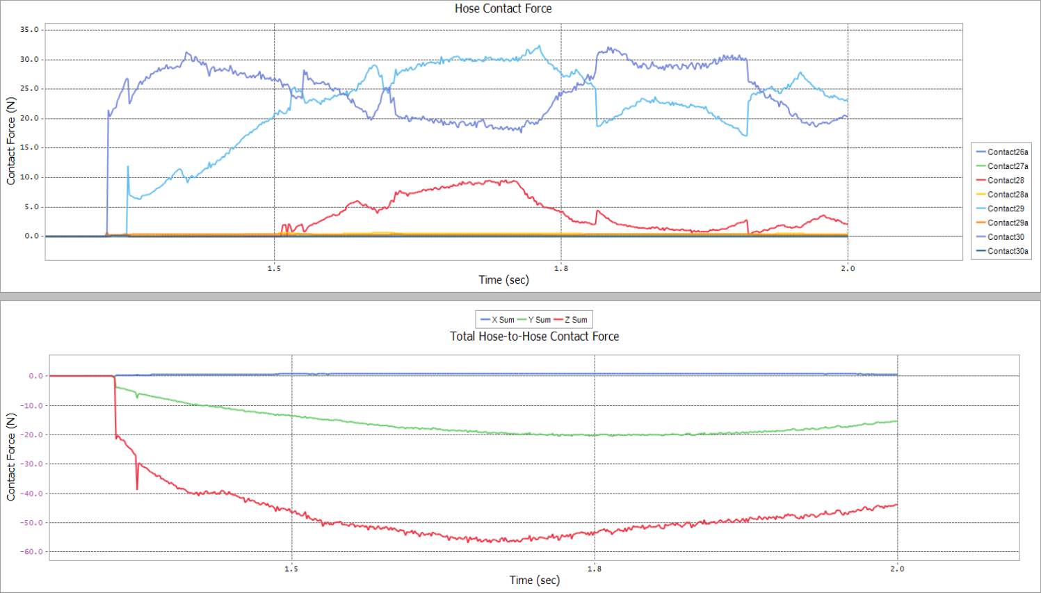
You should see the following two plots:
2.1.6. Converting VSTA Project into General Project
In this chapter, you will learn how to convert a VSTA project to a General project.
2.1.6.1. Task Objective
Learn how to use the code used in ProcessNet VSTA project into a ProceeNet General project by converting work.
2.1.6.2. Estimated Time to Complete
5 minutes
2.1.6.3. Editing the VSTA code
2.1.6.3.1. To open the VSTA project in Visual Studio:
Move to the C:\Users\<User Name>\Document\Visual Studio 2015\Project\4WD_Loader directory.
Open the 4WD_Loader.csproj file in the subfolder with Text Edit application except Visual Studio.
Delete <ProjectTypeGuids> in <PropertyGroup> as shown on below.
<PropertyGroup>
̶<̶P̶r̶o̶j̶e̶c̶t̶T̶y̶p̶e̶G̶u̶i̶d̶s̶>̶{̶A̶8̶6̶0̶3̶0̶3̶F̶-̶1̶F̶3̶F̶-̶4̶6̶9̶1̶-̶B̶5̶7̶E̶-̶5̶2̶9̶F̶C̶1̶0̶1̶A̶1̶0̶7̶}̶;̶{̶F̶A̶E̶0̶4̶E̶C̶0̶-̶3̶0̶1̶F̶-̶1̶1̶D̶3̶-̶B̶F̶4̶B̶-̶0̶0̶C̶0̶4̶F̶7̶9̶E̶F̶B̶C̶}̶<̶/̶P̶r̶o̶j̶e̶c̶t̶T̶y̶p̶e̶G̶u̶i̶d̶s̶>̶
<Configuration Condition=" '$(Configuration)' == '' ">Debug</Configuration>
<Platform Condition=" '$(Platform)' == '' ">AnyCPU</Platform>
<OutputType>Library</OutputType>
<NoStandardLibraries>false</NoStandardLibraries>
<RootNamespace>Loader</RootNamespace>
<AssemblyName>Loader</AssemblyName>
<ProjectGuid>{24C91D44-F891-47E7-B8A1-B422B35B5C7C}</ProjectGuid>
</PropertyGroup>
Save the file.
Open the 4WD_Loader.sln project on the upper directory in Visual Studio.
Note
If the edit file is opened in VSTA, the project for Visual Studio may not converted for Visual Studio.
2.1.6.3.2. To edit the code:
Delete a ThisApplication.designer.xml file in the sub of ThisApplication.cs on the Project Explorer window.
The ThisApplication.designer.xml file is only necessary in VSTA.
Delete a region by the name of VSTA generated code in ThisApplication.cs.
#region VSTA generated code

private void ThisApplication_Startup(object sender, EventArgs e)
{
    System.Threading.Thread.CurrentThread.CurrentCulture = System.Globalization.CultureInfo.InvariantCulture;
    MainWindow = new
    WinWrapper(System.Diagnostics.Process.GetCurrentProcess().MainWindowHandle);
}

private void ThisApplication_Shutdown(object sender, EventArgs e)
{

}

private void InternalStartup()
{
    this.Startup += new System.EventHandler(ThisApplication_Startup);
    this.Shutdown += new System.EventHandler(ThisApplication_Shutdown);
}
Add a code under the Common Variables as followings.
This is to access the RecurDyn application without using VSTA.
#region Common Variables

FunctionBay.RecurDyn.ProcessNet.RecurDyn.IRecurDynApp app = new
FunctionBay.RecurDyn.ProcessNet.RecurDyn.RDApplication();

static public IApplication application;
public IModelDocument modelDocument = null;
public IPlotDocument plotDocument = null;
public ISubSystem model = null;

public IReferenceFrame refFrame1 = null;
public IReferenceFrame refFrame2 = null;
#endregion
Edit the Initialize() function as followings.
#region Common Variables

FunctionBay.RecurDyn.ProcessNet.RecurDyn.IRecurDynApp app = new
FunctionBay.RecurDyn.ProcessNet.RecurDyn.RDApplication();

public void Initialize() //Initialize() will be called automatically before ProcessNet function call.
{
    application = app.RecurDynApplication as IApplication;
    ̶a̶p̶p̶l̶i̶c̶a̶t̶i̶o̶n̶ ̶=̶ ̶R̶e̶c̶u̶r̶D̶y̶n̶A̶p̶p̶l̶i̶c̶a̶t̶i̶o̶n̶ ̶a̶s̶ ̶I̶A̶p̶p̶l̶i̶c̶a̶t̶i̶o̶n̶;̶
    modelDocument = application.ActiveModelDocument;
    plotDocument = application.ActivePlotDocument;

    if (modelDocument == null & plotDocument == null)
    {
        application.PrintMessage("No model file");
        modelDocument = application.NewModelDocument("Examples");
    }
          if (modelDocument != null)
    {
        model = modelDocument.Model;
    }
}
From the Build menu, select Build Solution.