11.2. Track_LM Tutorial (eTemplate)
11.2.1. Getting Started
In this tutorial, the cells for Header Type and Parameter Definition cell are colored, but the color doesn’t affect the data at all.

Once after an eTemplate model (Excel file) is imported to RecurDyn, a new model needs to be created to import another eTemplate model (or a modified model).
This tutorial provides the Excel data to be copied and pasted. You can copy and paste the data with the left scissors mark to the Excel sheet
11.2.1.1. Objective
In this tutorial, you will make eTemplate model (Excel file) for Low-mobility tracked vehicle. Firstly you will use Master sheet of eTemplate model and HC (Hierarchy Connector). And you will create track system using eTemplate, and simulate it.
11.2.1.2. Audience
This tutorial is intended for intermediate users of RecurDyn who previously learned how to use TrackLM toolkit and basic operation of the Microsoft Excel.
11.2.1.3. Prerequisites
You should first work through the 3D Crank-Slider and Engine with Propeller tutorials, or the equivalent and TrackLM tutorial. We assume that you have a basic knowledge of physics.
11.2.1.4. Procedures
The tutorial is comprised of the following procedures. The estimated time to complete each procedure is shown in the table.
Procedures |
Time (minutes) |
Modifying Template_Format Sheet |
5 |
Using Master Sheet |
10 |
Creating Track_HC Sheet for eTemplate HC |
10 |
Creating bodies |
10 |
Creating track assembly |
10 |
Creating joints |
10 |
Changing settings |
10 |
Importing eTemplate file and running simulation |
10 |
Total |
75 |
11.2.1.5. Estimated Time to Complete
This tutorial takes approximately 75 minutes to complete.
11.2.2. Modifying Template_Format Sheet
11.2.2.1. Task Objective
Learn how to modify the Template_Format Sheet
11.2.2.2. Estimated Time to Complete
5 minutes
11.2.2.3. Modifying Template_Format Sheet
11.2.2.3.1. To modify Template_Format Sheet
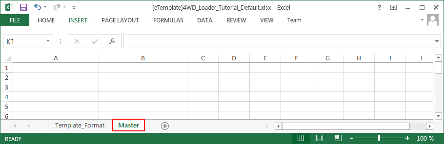
- On your Desktop, open the eTemplate file which exists in the same folder with this tutorial. ([eTemplate]Track_LM_Tutorial_Default.xlsx)(The file path: <InstallDir>\Help\Tutorial\eTemplate\CreationMode\TrackLM)
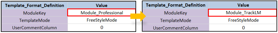
This file is the base file of eTemplate, which has the Template_Format Sheet. The purpose of this sheet is to decide how to handle this file.
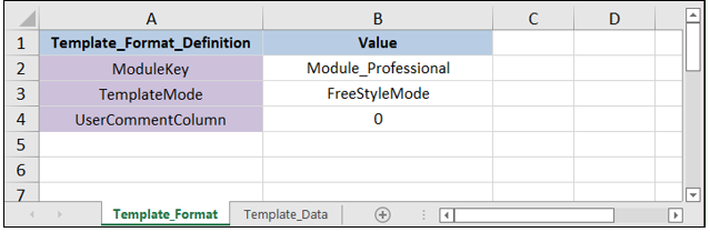
You should modify the ModuleKey setting to use this eTemplate file for Track_LM. Type Module_TrackLM instead of Module_Professional
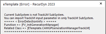
Now, this eTemplate file can be imported in TrackLM subsystem. But if you try to import this eTemplate file in other type of subsystem such as TrackHM or Chain, the below error message will be shown.
Tip
Copying the header and parameters using the eTemplate Helper
On the Customize tab, in the eTemplate group, click the Helper function to run the eTemplate Helper.
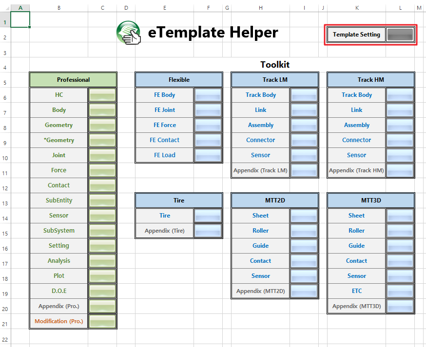
Click the Template Setting button.
Copy the header and parameters of the Template_Format sheet to the template.
Edit the values so that they fit the tutorial.
11.2.3. Using Master Sheet
11.2.3.1. Task Objective
Learn how to use Master Sheet
11.2.3.2. Estimated Time to Complete
10 minutes
11.2.3.3. Using Master Sheet
In this chapter, you will create several sheets to input many data systematically and you will create master sheet to handle several sheets. You will create the below sheets
Track_HC
Track_Body
Track_Assembly
Track_Joint
Track_Setting
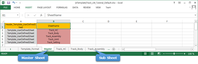
You can find Master Sheet next to Template_Format sheet. And this Master Sheet will include the information of the sheets which are used in this eTemplate model as below.
11.2.3.4. Editing Master Sheet
11.2.3.4.1. To use master sheet
eTemplate file must have Master Sheet. This tab is essential for RecurDyn to import an eTemplate file. So you must not remove or rename this sheet.
11.2.3.4.2. To edit sub sheets
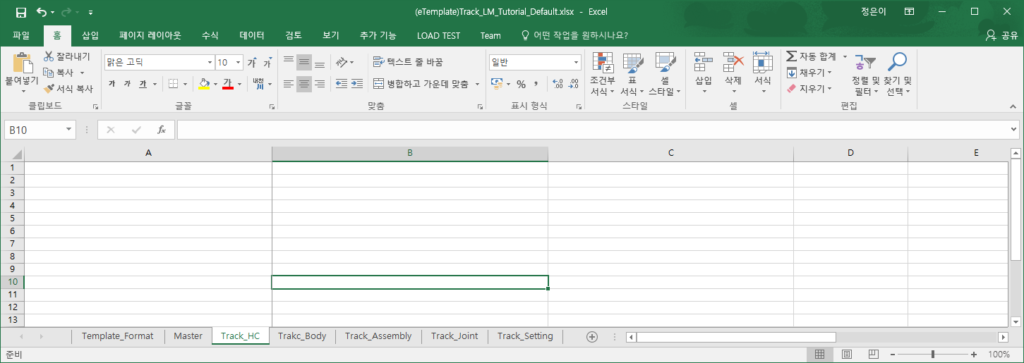
You will create 5 sheets.
Add 5 sheets in the Excel file and rename them (Track_HC, Track_Body, Track_Assembly, Track_Joint, Track_Setting)
11.2.3.4.3. To edit Master Sheet
To control sub sheets, Master Sheet must have Headers and Parameters.
Input Header_Template_UserDefinedSheet as Header Type and input SheetName as Parameter Type.
Input headers and parameters as below
Header_Template_UserDefinedSheet
SheetName
Template_UserDefinedSheet
Track_HC
Template_UserDefinedSheet
Track_Body
Template_UserDefinedSheet
Track_Assembly
Template_UserDefinedSheet
Track_Joint
Template_UserDefinedSheet
Track_Setting
The below image shows the Excel data after the above data are input.
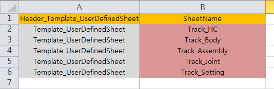
Please pay attention that the names used for parameters are same to the names of the sub sheets.
11.2.4. Creating Track_HC Sheet for eTemplate HC (Hierarchy Connector)
11.2.4.1. Task Objective
In this chapter you will learn how to create eTemplate HC (Hierarchy Connector) to be used in the later chapters. The data will be input in Track_HC Sheet
11.2.4.2. Estimated Time to Complete
10 minutes
11.2.4.3. Understanding Track System
11.2.4.3.1. To construct Track System
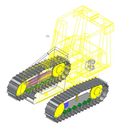
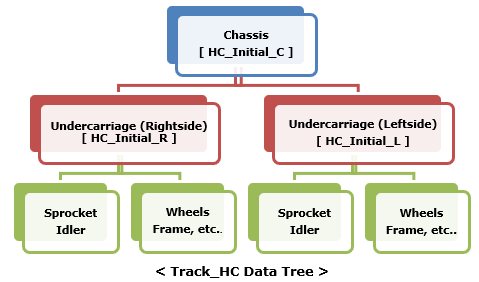
Track System can be roughly divided into 3 parts. Chassis, Undercarriage (Right side), Undercarriage (Left side).
HC (Hierarchy Connector) is used to define the relative position and orientation.
In this tutorial, HCs are defined relative to the position of Chassis. In other words, if the position of Chassis is moved, the entire Track System is moved.
11.2.4.4. Editing Track_HC Sheet
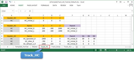
11.2.4.4.1. To input data in Track_HC Sheet
Select Track_HC Sheet.

Input HC_Initial_C for the position of Chassis. This will be used as reference position of the entire Track System.
Header_HC
Name
X
Y
Z
HC
HC_Initial_C
0
0
0
Input HC_Initial_R and HC_Initial_L for undercarriages. Parent means that the position of these HCs are relative to HC_Initial_C.
Header_HC
Name
X
Y
Z
Parent
HC
HC_Initial_R
250
-300
1000
HC_Initial_C
HC
HC_Initial_L
250
-300
-1000
HC_Initial_C
Now you will Input the other HCs as below for the components of the right side undercarriage. So the parent must be HC_Initial_R.
For sprocket, position and orientation need to be defined to avoid the interference between the teeth of Sprocket and track links.
Header_HC
Name
X
Y
Z
Parent
EA
EB
EG
HC
HC_Sprocket_R
-2900
0
0
HC_Initial_R
89
0
-90
For the other parts except sprocket, only position needs to be input.
Header_HC
Name
X
Y
Z
Parent
HC
HC_Idler_R
-700
0
0
HC_Initial_R
HC
HC_Wheel_1_R
-2460
-250
0
HC_Initial_R
HC
HC_Wheel_2_R
-2220
-250
0
HC_Initial_R
HC
HC_Wheel_3_R
-1930
-250
0
HC_Initial_R
HC
HC_Wheel_4_R
-1640
-250
0
HC_Initial_R
HC
HC_Wheel_5_R
-1350
-250
0
HC_Initial_R
HC
HC_Wheel_6_R
-1110
-250
0
HC_Initial_R
HC
HC_Carrier_Roller_1_R
-1780
360
0
HC_Initial_R
HC
HC_Tensioner_R
0
0
0
HC_Initial_R
HC
HC_Frame_R
0
0
0
HC_Initial_R
HC
HC_Frame_Fixed_R
-1780
0
0
HC_Initial_R
HC
HC_Tensioner_Fixed_R
-1200
0
0
HC_Initial_R
In this time, you will input data for left side undercarriage. Here you can find the advantage of using eTemplate. To create left side undercarriage, you just need to copy and paste the data for right side undercarriage and just change the Parent from HC_Initial_R to HC_Initial_L and change the HC Name R to L
Header_HC
Name
X
Y
Z
Parent
EA
EB
EG
HC
HC_Sprocket_L
-2900
0
0
HC_Initial_L
89
0
-90
Header_HC
Name
X
Y
Z
Parent
HC
HC_Idler_L
-700
0
0
HC_Initial_L
HC
HC_Wheel_1_L
-2460
-250
0
HC_Initial_L
HC
HC_Wheel_2_L
-2220
-250
0
HC_Initial_L
HC
HC_Wheel_3_L
-1930
-250
0
HC_Initial_L
HC
HC_Wheel_4_L
-1640
-250
0
HC_Initial_L
HC
HC_Wheel_5_L
-1350
-250
0
HC_Initial_L
HC
HC_Wheel_6_L
-1110
-250
0
HC_Initial_L
HC
HC_Carrier_Roller_1_L
-1780
360
0
HC_Initial_L
HC
HC_Tensioner_L
0
0
0
HC_Initial_L
HC
HC_Frame_L
0
0
0
HC_Initial_L
HC
HC_Frame_Fixed_L
-1780
0
0
HC_Initial_L
HC
HC_Tensioner_Fixed_L
-1200
0
0
HC_Initial_L
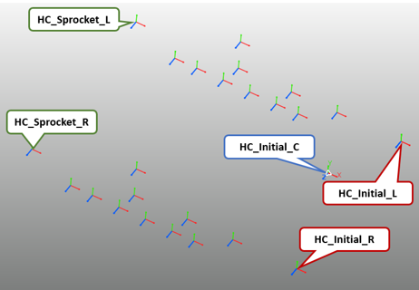
Now, Track_HC Sheet is completed.
Save the Excel file and import it into RecurDyn. How to import eTemplate file is explained in chapter 9.
The below image shows the result when you import the eTemplate file.
11.2.5. Creating Bodies
11.2.5.1. Task Objective
In this chapter, you will learn how to import CAD files and create track bodies
11.2.5.2. Estimated Time to Complete
10 minutes
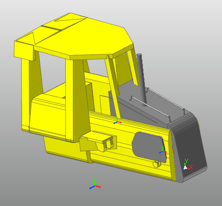
11.2.5.3. Creating Chassis Bodies
Please select Track_Body Sheet.

- Input the below information to import Chassis.x_t.(The file path: <InstallDir>\Help\Tutorial\Toolkit\eTemplate\CreationMode\Track_LM)
Header_Body_Import
Name
RefFrame
FileName
UseAutoMerge
Body_Import
Chassis
HC_Initial_C
Chassis.x_t
True
There are 2 options for Import. UseAutoMerge is the option to decide if you want to merge the imported files automatically. | Another option, which is not used in this tutorial is FilePath, | which is used when the CAD file exists in the different path from the path where eTemplate File (Excel file) is located.
You can use absolute coordinate input or relative coordinate input for RefFrame. You will use the relative coordinate input using HC_Initial_C which you created in the previous chapter. It means that Chassis uses the marker HC_Initial_C as a reference frame.
Tip
Absolute coordinate input vs. Relative coordinate inputAbsolute coordinate input uses numbers and commas directly. (e.g. 100, 200,300) relative coordinate input uses the existing marker name (ex : HC_Initial_C )
11.2.5.4. Creating Right-side Undercarriage
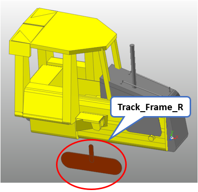
11.2.5.4.1. To create a track frame:
You will create a track frame where the track bodies will be fixed.
- Import Track_Frame.x_t.(The file path: <InstallDir>\Help\Tutorial\Toolkit\eTemplate\CreationMode\Track_LM)
Input HC_Frame_R for RefFrame to make the track frame on the right side. (Refer to Track_HC Data Tree in chapter 4)
Header_Body_Import
Name
RefFrame
FileName
UseAutoMerge
Body_Import
Track_Frame_R
HC_Frame_R
Track_Frame.x_t
True
Save the Excel file and import it into RecurDyn then the below model is created.
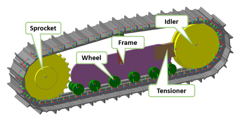
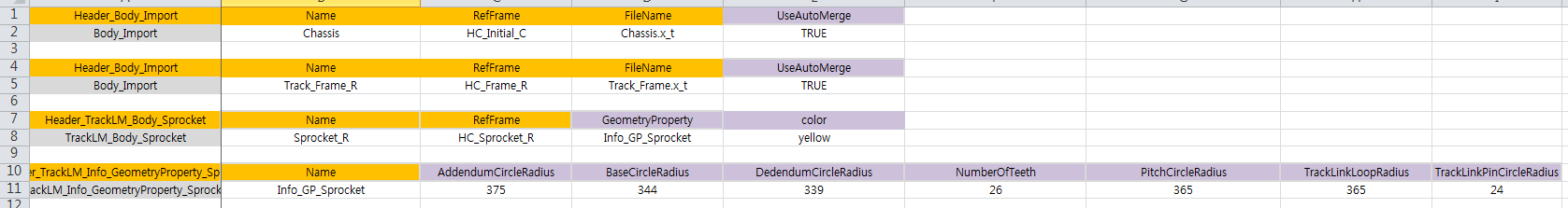
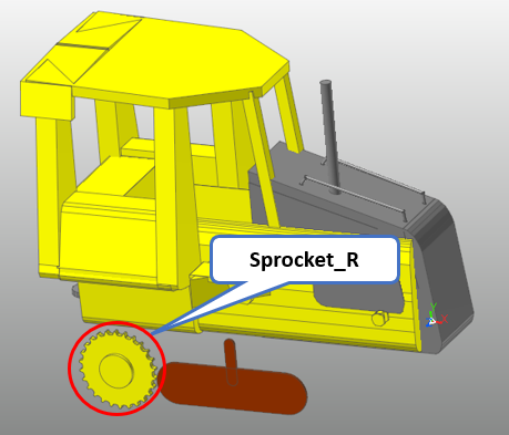
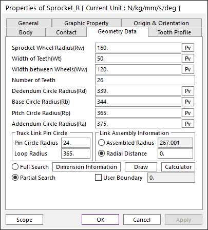
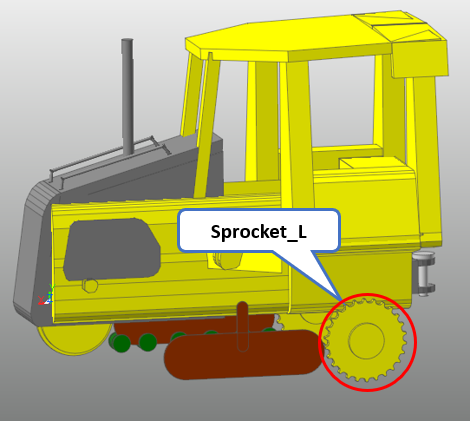
11.2.5.4.2. To create a sprocket:
You will create a sprocket, one of the track bodies.
Header_TrackLM_Body_Sprocket
Name
RefFrame
GeometryProperty
color
TrackLM_Body_Sprocket
Sprocket_R
HC_Sprocket_R
Info_GP_Sprocket
yellow
2 options, GeometryProperty and color are used here. If options are not input, RecurDyn uses the default values.
To use GeometryProperty, you need to create an Information for it. Input Info_GP_Sprocket for GeometryProperty. You will create an Information, whose name is Info_GP_Sprocket below.
Input yellow for color.
To create an Information, Info_GP_Sprocket for GeometryProperty, please input as below.
Header_TrackLM_Info_GeometryProperty_Sprocket
Name
AddendumCircleRadius
BaseCircleRadius
TrackLM_Info_GeometryProperty_Sprocket
Info_GP_Sprocket
375
344
DedendumCircleRadius
NumberOfTeeth
PitchCircleRadius
TrackLinkLoopRadius
TrackLinkPinCircleRadius
339
26
365
365
24
The above data needs to be input in the same line as below.
Save the Excel file and import it into RecurDyn then the below model is created.
Tip
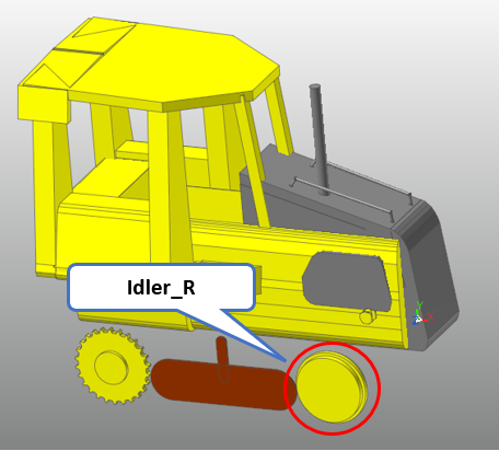
11.2.5.4.3. To create an idler:
You will create an idler, one of the track bodies.
Header_TrackLM_Body_FlangeCenter
Name
RefFrame
GeometryProperty
color
TrackLM_Body_FlangeCenter
Idler_R
HC_Idler_R
Info_GP_Idler
yellow
2 options, GeometryProperty and color are used here. If options are not input, RecurDyn uses the default values.
To use GeometryProperty, you need to create an Information for it. Input Info_GP_Idler for GeometryProperty. You will create an Information, whose name is Info_GP_Idler below.
To create an Information, Info_GP_Idler for GeometryProperty, please input as below.
Header_TrackLM_Info_GeometryProperty_FlangeCenter
Name
InnerFlangeRadius
WheelRadius
TrackLM_Info_GeometryProperty_FlangeCenter
Info_GP_Idler
350
320
Save the Excel file and import it into RecurDyn then the below model is created.
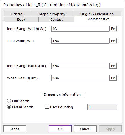
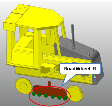
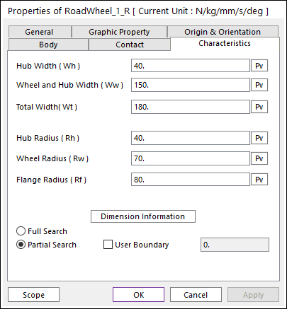
11.2.5.4.4. To create wheels:
You will create 6 wheels.
Header_TrackLM_Body_FlangeSingle
Name
RefFrame
GeometryProperty
color
TrackLM_Body_FlangeSingle
RoadWheel_1_R
HC_Wheel_1_R
Info_GP_Wheel
green
TrackLM_Body_FlangeSingle
RoadWheel_2_R
HC_Wheel_2_R
Info_GP_Wheel
green
TrackLM_Body_FlangeSingle
RoadWheel_3_R
HC_Wheel_3_R
Info_GP_Wheel
green
TrackLM_Body_FlangeSingle
RoadWheel_4_R
HC_Wheel_4_R
Info_GP_Wheel
green
TrackLM_Body_FlangeSingle
RoadWheel_5_R
HC_Wheel_5_R
Info_GP_Wheel
green
TrackLM_Body_FlangeSingle
RoadWheel_6_R
HC_Wheel_6_R
Info_GP_Wheel
green
To use GeometryProperty, you need to create an Information for it. Input Info_GP_Wheel for GeometryProperty. You will create an Information, whose name is Info_GP_Wheel below.
To create an Information, Info_GP_Wheel for GeometryProperty, please input as below.
Header_TrackLM_Info_GeometryProperty_FlangeSingle
Name
FlangeRadius
HubRadius
WheelRadius
TrackLM_Info_GeometryProperty_FlangeSingle
Info_GP_Wheel
80
40
70
Save the Excel file and import it into RecurDyn then the below model is created.
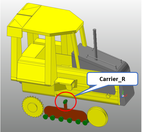
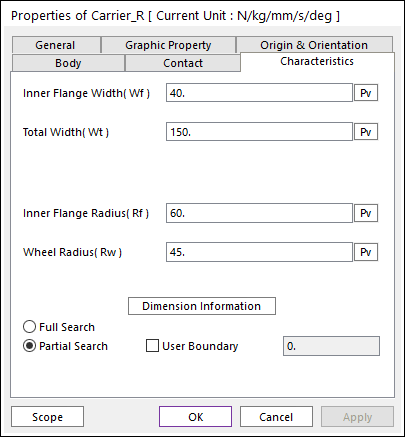
11.2.5.4.5. To create a carrier roller:
You will create a carrier roller, one of the track bodies.
Header_TrackLM_Body_FlangeCenter
Name
RefFrame
GeometryProperty
color
TrackLM_Body_FlangeCenter
Carrier_R
HC_Carrier_Roller_1_R
Info_GP_Carrier
green
To create an Information, Info_GP_Carrier for GeometryProperty, please input as below
Header_TrackLM_Info_GeometryProperty_FlangeCenter
Name
InnerFlangeRadius
WheelRadius
TrackLM_Info_GeometryProperty_FlangeCenter
Info_GP_Carrier
60
45
Save the Excel file and import it into RecurDyn then the below model is created.
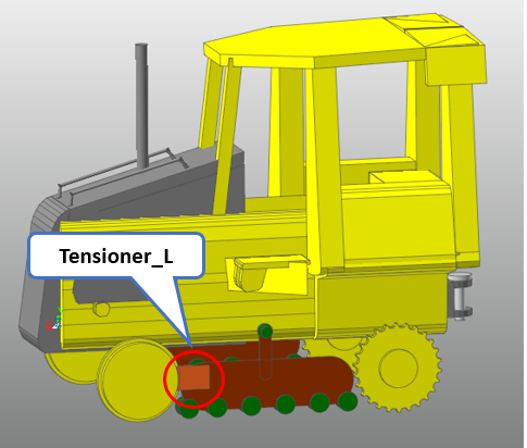
11.2.5.4.6. To create a tensioner:
You will create a tensioner, one of the track bodies.
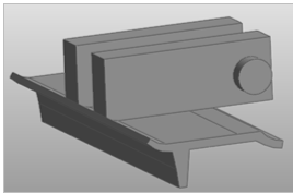
- Import Tensioner.x_t.(The file path: <InstallDir>\Help\Tutorial\Toolkit\eTemplate\CreationMode\Track_LM)
Header_Body_Import
Name
RefFrame
FileName
UseAutoMerge
Body_Import
Tensioner_R
HC_Tensioner_R
Tensioner.x_t
True
Save the Excel file and import it into RecurDyn then the below model is created.
11.2.5.5. Creating Left-side Undercarriage
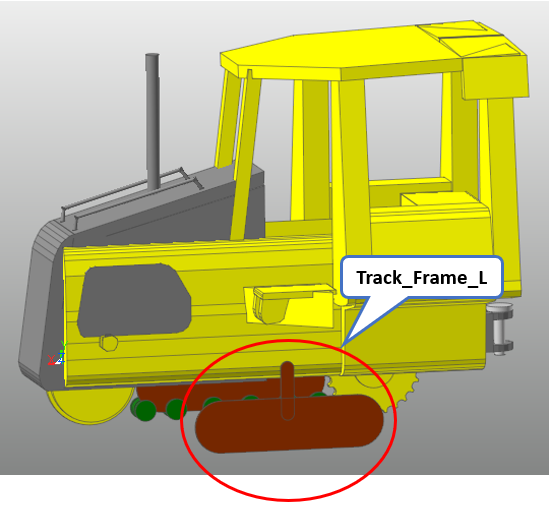
11.2.5.5.1. To create a track frame:
You will create a track frame where the track bodies will be fixed.
- Import Track_Frame.x_t.(The file path: <InstallDir>\Help\Tutorial\Toolkit\eTemplate\CreationMode\Track_LM)
Input HC_Frame_L for RefFrame to make the track frame on the left side. (Refer to Track_HC Data Tree in chapter 4)
Header_Body_Import
Name
RefFrame
FileName
UseAutoMerge
Body_Import
Track_Frame_L
HC_Frame_L
Track_Frame.x_t
True
Save the Excel file and import it into RecurDyn then the below model is created.
11.2.5.5.2. To create a sprocket:
You will create a sprocket, one of the track bodies.
Header_TrackLM_Body_Sprocket
Name
RefFrame
GeometryProperty
color
TrackLM_Body_Sprocket
Sprocket_L
HC_Sprocket_L
Info_GP_Sprocket
yellow
To use GeometryProperty, you need to create an Information for it. Input Info_GP_Sprocket for GeometryProperty. You already created Info_GP_Sprocket above so that you don’t need to create again.
The above data needs to be input in the same line as below.
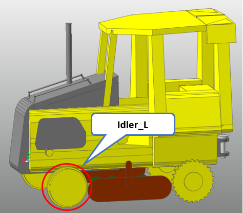
11.2.5.5.3. To create an idler:
You will create an idler, one of the track bodies.
Header_TrackLM_Body_FlangeCenter
Name
RefFrame
GeometryProperty
color
TrackLM_Body_FlangeCenter
Idler_L
HC_Idler_L
Info_GP_Idler
yellow
You already created Info_GP_Idler above so that you don’t need to create again.
Save the Excel file and import it into RecurDyn then the below model is created.
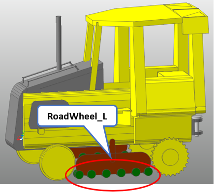
11.2.5.5.4. To create wheels:
You will create 6 wheels.
Header_TrackLM_Body_FlangeSingle
Name
RefFrame
GeometryProperty
color
TrackLM_Body_FlangeSingle
RoadWheel_1_L
HC_Wheel_1_L
Info_GP_Wheel
green
TrackLM_Body_FlangeSingle
RoadWheel_2_L
HC_Wheel_2_L
Info_GP_Wheel
green
TrackLM_Body_FlangeSingle
RoadWheel_3_L
HC_Wheel_3_L
Info_GP_Wheel
green
TrackLM_Body_FlangeSingle
RoadWheel_4_L
HC_Wheel_4_L
Info_GP_Wheel
green
TrackLM_Body_FlangeSingle
RoadWheel_5_L
HC_Wheel_5_L
Info_GP_Wheel
green
TrackLM_Body_FlangeSingle
RoadWheel_6_L
HC_Wheel_6_L
Info_GP_Wheel
green
You already created Info_GP_Wheel above so that you don’t need to create again.
Save the Excel file and import it into RecurDyn then the below model is created.
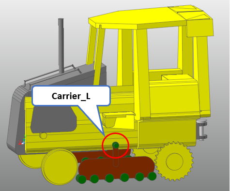
11.2.5.5.5. To create a carrier roller:
You will create a carrier roller, one of the track bodies.
Header_TrackLM_Body_FlangeCenter
Name
RefFrame
GeometryProperty
color
TrackLM_Body_FlangeCenter
Carrier_L
HC_Carrier_Roller_1_L
Info_GP_Carrier
green
You already created Info_GP_Carrier above so that you don’t need to create again.
Save the Excel file and import it into RecurDyn then the below model is created.
11.2.5.5.6. To create a tensioner:
You will create a tensioner, one of the track bodies.
- Import Tensioner.x_t.(The file path: <InstallDir>\Help\Tutorial\Toolkit\eTemplate\CreationMode\Track_LM)
Header_Body_Import
Name
RefFrame
FileName
UseAutoMerge
Body_Import
Tensioner_L
HC_Tensioner_L
Tensioner.x_t
True
Save the Excel file and import it into RecurDyn then the below model is created.
Now, you completed creating both of undercarriages.
11.2.6. Creating Track Assembly
11.2.6.1. Task Objective
In this chapter, you will create a clone link and create track assembly using it.
11.2.6.2. Estimated Time to Complete
10 minutes
11.2.6.3. Creating Clone Link
11.2.6.3.1. To create a clone link
Please select Track_Assembly Sheet.

Before creating track assembly, clone link needs to be created in advance.
Input the below information to create clone link.
Header_TrackLM_Clone_Link
Name
GeometryProperty
LinkGrouserProfile
TrackLM_Clone_Link
LM_Clone_Link
Info_GP_Link
Info_LinkGrouserProfile
2 options, GeometryProperty and LinkGrouserProfile are used here. If options are not input, RecurDyn uses the default values.
To create an Information, Info_GP_Link for GeometryProperty, please input as below.
PinRadius
RightLength
LeftPinPosition
RightPinPosition
24
119.5
-88.5,39
88.5,39
The above data needs to be input in the same line as below.
FileNameForGrouserProfile is the profile data to represent the shape of the grouser of a clonk link. You will import Grouser1.mat for it and this file must exist in the same path where the eTemplate file is located.
Header_TrackLM_Info_LinkGrouserProfile
Name
FileNameForGrouserProfile
TrackLM_Info_LinkGrouserProfile
Info_LinkGrouserProfile
Grouser1.mat
Save the Excel file and import it into RecurDyn then the below model is created.
11.2.6.4. Creating Track Assembly
11.2.6.4.1. Creating Right-side Track Assembly
To create track assembly, the clone link which you just created before will be used.
Input the track bodies in order which consist of track assembly for the PassingEntityList. Input / between each track body.
Input PassingEntityList according to the below order.
Sprocket RoadWheel (1~6) Idler Carrier.
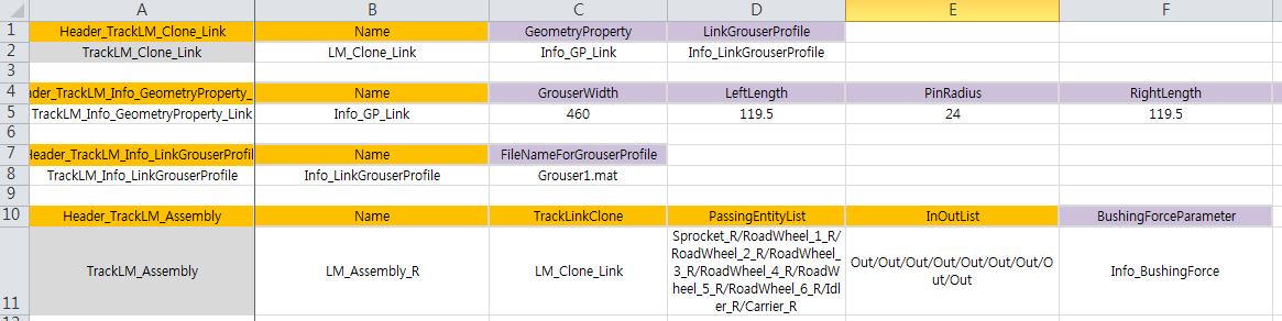
Header_TrackLM_Assembly
Name
TrackLinkClone
PassingEntityList
InOutList
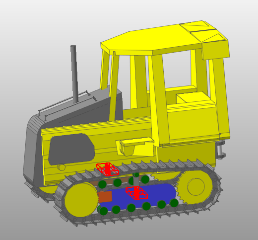
TrackLM_Assembly
LM_Assembly_R
LM_Clone_Link
Sprocket_R/Road Wheel_1_R/Road Wheel_2_R/Road Wheel_3_R/Road Wheel_4_R/Road Wheel_5_R/Road Wheel_6_R/Idler_R/Carrier_R
Out/Out/Out/Out/Out/Out/Out/Out/Out
InOutList the parameter to decide if the track link is located inside or outside of Passing Entities. Please be careful that the number of the data of PassingEntityList must be same to the number of the InOutList data.
To create an Information, Info_BushingForce for BushingForceParameter, please input as below.
BushingForceParameter
Info_BushingForce
The data you input so far will look like as below
To use GeometryProperty, you need to create an Information for it. Input Info_BushingForce for BushingForceParameter. You will create an Information, whose name is Info_GP_Idler below.
Header_TrackLM_Info_Assembly_BushingForce
Name
RotationPresetAngle
TrackLM_Info_Assembly_BushingForce
Info_BushingForce
10
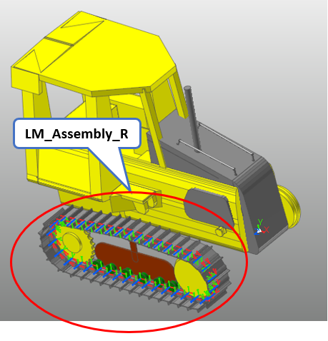
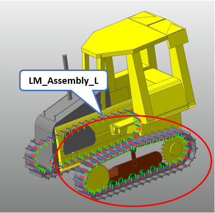
Save the Excel file and import it into RecurDyn then the below model is created.
11.2.6.4.2. Creating Left-side Track Assembly
To create track assembly, the clone link which you just created before will be used.
Input the track bodies in order which consist of track assembly for the PassingEntityList. Input / between each track body. Please be careful that you need to input the track body names for left-side track assembly.
Header_TrackLM_Assembly
Name
TrackLinkClone
PassingEntityList
InOutList
TrackLM_Assembly
LM_Assembly_L
LM_Clone_Link
Sprocket_L/Road Wheel_1_L/Road Wheel_2_L/Road Wheel_3_L/Road Wheel_4_L/Road Wheel_5_L/Road Wheel_6_L/Idler_L/Carrier_L
Out/Out/Out/Out/Out/Out/Out/Out/Out
Please be careful that the number of the data of PassingEntityList must be same to the number of the InOutList data.
To use GeometryProperty, you need to create an Information for it. Input Info_BushingForce for BushingForceParameter. You will create an Information, whose name is Info_GP_Idler below.
You already created Info_BushingForce above so that you don’t need to create again.
BushingForceParameter
Info_BushingForce
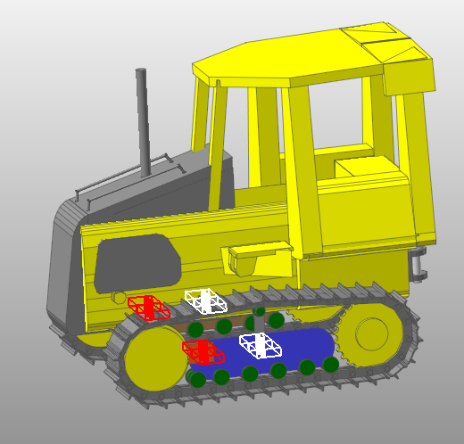
Save the Excel file and import it into RecurDyn then the below model is created.
11.2.7. Creating Joints
11.2.7.1. Task Objective
In this chapter, you will learn how to create joints to connect the bodies you created. Also you will create a ground for simulation.
11.2.7.2. Estimated Time to Complete
10 minutes
11.2.7.3. Creating Fixed Joints
11.2.7.3.1. To create Fixed Joint between Chassis and Track Frame
Please select Track_Joint Sheet.

You will create 2 fixed joints to fix both Track Frames on Chassis.
Input Chassis for BaseEntity and Track_Frame_R and Track_Frame_L for ActionEntity.
Input HC_Frame_Fixed_R and HC_Frame_Fixed_L for each of RefFrame.
Header_JointEx_Fixed
Name
BaseEntity
ActionEntity
RefFrame
JointEx_Fixed
Fix_Track_Frame_R
Chassis
Track_Frame_R
HC_Frame_Fixed_R
JointEx_Fixed
Fix_Track_Frame_L
Chassis
Track_Frame_L
HC_Frame_Fixed_L
Save the Excel file and import it into RecurDyn then the below model is created.
You will create 2 fixed joints to connect both Tensioners on each Track Frame.
Input Track_Frame_R and Track_Frame_L for BaseEntity and Tensioner_R and Tensioner_L for ActionEntity.
Input HC_Tensioner_Fixed_R and HC_Tensioner_Fixed_R for each of RefFrame.
Header_JointEx_Fixed
Name
BaseEntity
ActionEntity
RefFrame
JointEx_Fixed
Fix_Tensioner_R
Track_Frame_R
Tensioner_R
HC_Tensioner_Fixed_R
JointEx_Fixed
Fix_Tensioner_L
Track_Frame_L
Tensioner_L
HC_Tensioner_Fixed_L
Save the Excel file and import it into RecurDyn then the below model is created.
11.2.7.4. Creating Revolute Joints
11.2.7.4.1. Revolute Joint creation and motion-defined
You will create 2 revolute joints to connect both sprockets on each Track Frame.
Input Track_Frame_R and Track_Frame_L for BaseEntity and Sprocket_R and Sprocket_L for ActionEntity.
Input HC_Sprocket_R and HC_Sprocket_R for each of RefFrame
Header_JointEx_Revolute
Name
BaseEntity
ActionEntity
RefFrame
JointEx_Revolute
Rev_Sprocket_R
Track_Frame_R
Sprocket_R
HC_Sprocket_R
JointEx_Revolute
Rev_Sprocket_L
Track_Frame_L
Sprocket_L
HC_Sprocket_L
Each of revolute joint has Motion, so that the below option needs to be input.
UseMotion
Motion
TRUE
Info_Joint_01
TRUE
Info_Joint_01
Since the motions use the option, you need to create an Information, whose name is Info_Joint_01 as below.
Firstly, you need to create an expression to be used for Motion either.
Header_SubEntity_Expression
Name
ExpressionText
SubEntity_Expression
Exp_Sprocket_Vel
-STEP(TIME, 0.1, 0, 1, 360D)
Create an Information whose name is Info_Joint_01 and input MotionType and MotionCondition as below.
Header_Info_JointMotion
Name
Expression
MotionType
MotionCondition
Info_JointMotion
Info_Joint_01
Exp_Sprocket_Vel
Standard
Velocity
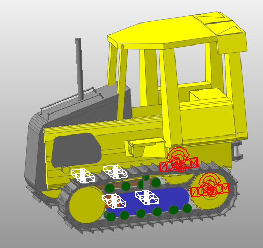
Save the Excel file and import it into RecurDyn then the below model is created.
You will create 2 revolute joints to connect track bodies on each Track Frame.
11.2.7.4.2. To create Revolute Joint
Input as below to connect wheels and track frames for right-side undercarriage
Header_JointEx_Revolute
Name
BaseEntity
ActionEntity
RefFrame
JointEx_Revolute
Rev_Wheel_1_R
Track_Frame_R
RoadWheel_1_R
HC_Wheel_1_R
JointEx_Revolute
Rev_Wheel_2_R
Track_Frame_R
RoadWheel_2_R
HC_Wheel_2_R
JointEx_Revolute
Rev_Wheel_3_R
Track_Frame_R
RoadWheel_3_R
HC_Wheel_3_R
JointEx_Revolute
Rev_Wheel_4_R
Track_Frame_R
RoadWheel_4_R
HC_Wheel_4_R
JointEx_Revolute
Rev_Wheel_5_R
Track_Frame_R
RoadWheel_5_R
HC_Wheel_5_R
JointEx_Revolute
Rev_Wheel_6_R
Track_Frame_R
RoadWheel_6_R
HC_Wheel_6_R
Input as below to connect carrier to track frame.
Header_JointEx_Revolute
Name
BaseEntity
ActionEntity
RefFrame
JointEx_Revolute
Rev_FlangeCenter_1_R
Track_Frame_R
Carrier_R
HC_Carrier_Roller_1_R
Input as below to connect tensioner to idler.
Header_JointEx_Revolute
Name
BaseEntity
ActionEntity
RefFrame
JointEx_Revolute
Rev_Idler_R
Idler_R
Tensioner_R
HC_Idler_R
Input as below for left-side undercarriage either.
Header_JointEx_Revolute
Name
BaseEntity
ActionEntity
RefFrame
JointEx_Revolute
Rev_Wheel_1_L
Track_Frame_L
RoadWheel_1_L
HC_Wheel_1_L
JointEx_Revolute
Rev_Wheel_2_L
Track_Frame_L
RoadWheel_2_L
HC_Wheel_2_L
JointEx_Revolute
Rev_Wheel_3_L
Track_Frame_L
RoadWheel_3_L
HC_Wheel_3_L
JointEx_Revolute
Rev_Wheel_4_L
Track_Frame_L
RoadWheel_4_L
HC_Wheel_4_L
JointEx_Revolute
Rev_Wheel_5_L
Track_Frame_L
RoadWheel_5_L
HC_Wheel_5_L
JointEx_Revolute
Rev_Wheel_6_L
Track_Frame_L
RoadWheel_6_L
HC_Wheel_6_L
JointEx_Revolute
Rev_FlangeCenter_1_L
Track_Frame_L
Carrier_L
HC_Carrier_Roller_1_L
JointEx_Revolute
Rev_Idler_L
Idler_L
Tensioner_L
HC_Idler_L
Save the Excel file and import it into RecurDyn then the below model is created.
Now, you completed creating track system.
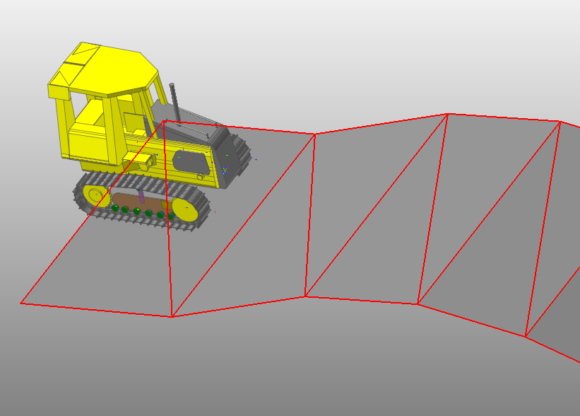
11.2.7.5. Creating Ground
In addition to the track system, you will import road where the track system will
You will Input the below information to import Terrain_Outline.rdf. This file must exist in the same path where the eTemplate file is located. If you want to use different road, you can use different rdf file.
Header_RoadData_Import
Name
FileName
RoadData_Import
Terrain_Outline
Terrain_Outline.rdf
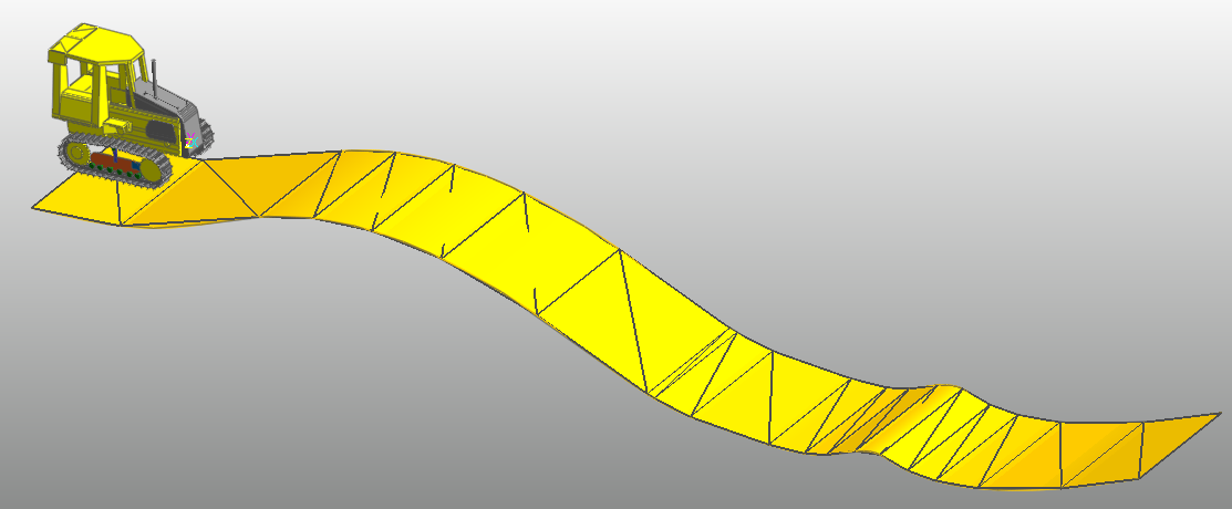
Save the Excel file and import it into RecurDyn then the below model is created.
11.2.8. Changing Settings
11.2.8.1. Task Objective
In this chapter, you will change some settings such as Dynamic Analysis Setting, Icon/Marker size and etc.
11.2.8.2. Estimated Time to Complete
10 minutes
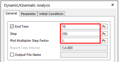
11.2.8.3. Changing Dynamic Analysis Settings
11.2.8.3.1. To change parameters for dynamic analysis:
Please select Track_Setting Sheet.

It is possible to change Simulation Time (End Time), Simulation Step (Step) and Plot Multiplier Step Factor using eTemplate.
Input as below.
Header_Setting_DynamicAnalysis
SimulationTime
SimulationStep
PlotMultiplierStepFactor
Setting_DynamicAnalysis
10
250
1
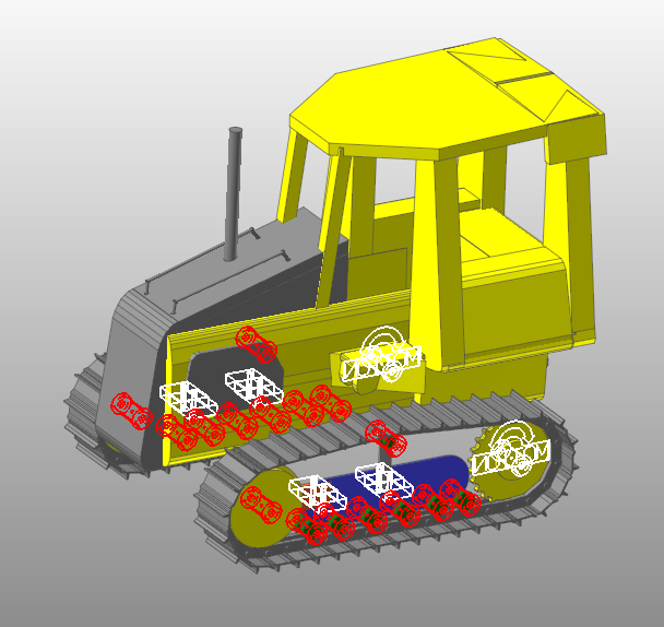
11.2.8.4. Changing Display Settings
11.2.8.4.1. To change Icon/Marker size:
It is possible to change Icon/Marker size using eTemplate.
Input as below.
Header_Setting_Icon
IconSize
MarkerSize
Setting_Icon
10
10
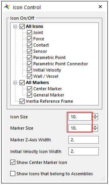
The above settings are same to below.
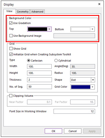
11.2.8.4.2. To change Background Color:
It is possible to change Background Color using eTemplate.
Input as below.
Header_Setting_BackGround
BottomColor
TopColor
UseGradation
Setting_BackGround
White
Black
TRUE
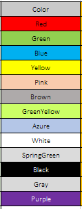
Please refer to the Appendix in the eTemplate manual for the color options you can use. Of course it is possible to input more colors using RecurDyn GUI.
11.2.9. Importing eTemplate File and Running Simulation
11.2.9.1. Task Objective
In this chapter, you will import the completed eTemplate file and run simulation.
11.2.9.2. Estimated Time to Complete
10 minutes
11.2.9.3. Importing eTemplate File
11.2.9.3.1. To import eTemplate file:
Launch RecurDyn
Input Track_LM_Tutorial for the name of the new model.
11.2.9.3.2. To executing eTemplate:
Since ModuleKey is set as Module_TrackLM, the eTemplate file can be imported only in Track_LM subsystem.
From the Subsystem Toolkit group of the Toolkit tab, click the Track(LM) function.
To execute eTemplate, from the eTemplate group of the Customize tab, click the Run function.
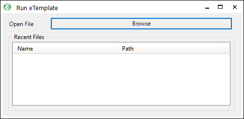
To import the eTemplate file (Excel file) created in the previous chapters, click Browse. The other files such as *.x_t, *.mat must exist in the same path with the eTemplate file.
11.2.9.4. Performing Analysis
11.2.9.4.1. To perform Analysis:
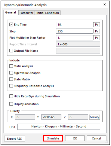
Click the Dynamic / Kinematic Analysis function in the Simulation Type group under the Analysis tab.
The Dynamic/Kinematic Analysis dialog box appears.
You can see that the parameters you changed in the previous chapter are applied.
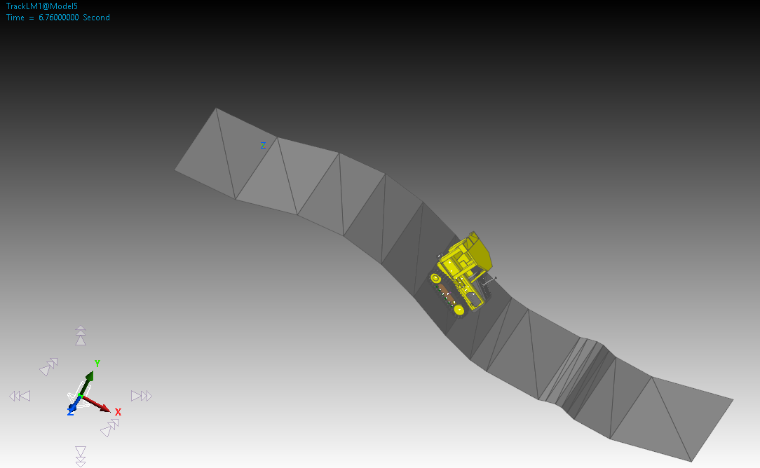
Click Simulate.
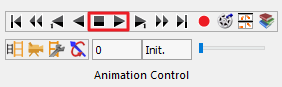
Animate the model using the Play tool on the Animation Toolbar. Refer to TrackLM tutorial for more information on playing an animation.
Click the Stop tool to reset the model.