9.2. Forklift with Roller Chain Tutorial (Chain)
9.2.1. Getting Started
9.2.1.1. Objective
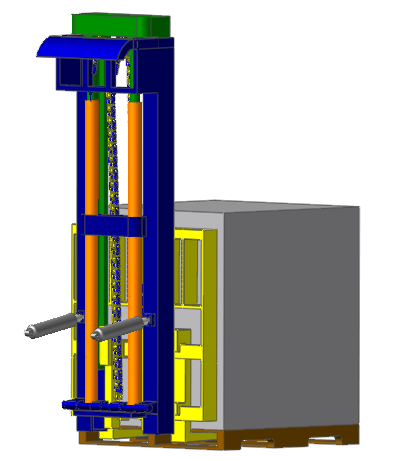
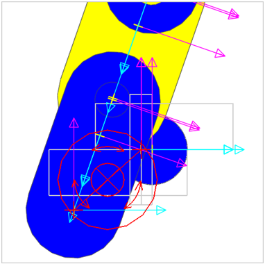
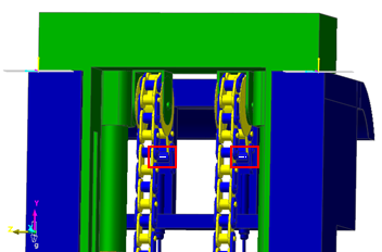
This tutorial will help you learn how to simulate the chain-drive of a forklift using the RecurDyn/Chain toolkit. You will generate animations and plots, which will provide insight into the function of the model and verify your intuitive understanding of the chain system. The completed chain forklift system is shown below:
The RecurDyn/Chain toolkit lets you model chain and pulley systems of various types and configurations. In this tutorial you will use Roller Links and Rollers. RecurDyn automatically creates the contacts between these entities when you assemble the chain system. You can also use other RecurDyn bodies, constraints, and force elements to model the chain systems. Once the chain subsystem is built, we will combine it with an existing forklift model and run some simulations.
9.2.1.2. Audience
This tutorial is intended for experienced users of RecurDyn who previously learned how to create geometry, joints, and force entities. All new tasks are explained carefully.
9.2.1.3. Prerequisites
You should first work through the 3D Crank-Slider and Engine with Propeller tutorials, or the equivalent. We assume that you have a basic knowledge of physics.
9.2.2. Creating the Subsystem
9.2.2.1. Task Objective
Using an existing base model, learn how to create a chain subsystem and bring the subsystem to approximately steady-state conditions. In the next chapter, you will assemble the chain to the forklift and run a simulation.
9.2.2.2. Estimated Time to Complete
20 minutes
9.2.2.3. Starting RecurDyn
9.2.2.3.1. To start RecurDyn and open the base model:
On your Desktop, double-click the RecurDyn. RecurDyn starts and the Start RecurDyn dialog box appears.
Close Start RecurDyn dialog box as we will be using an existing model.
From the File menu, choose the Open function.
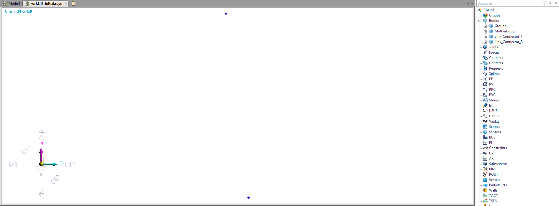
- Select the file ForkLift_Initial.rdyn.(The file path: <InstallDir>\Help\Tutorial\Toolkit\ChainForkliftWithRollerChain)
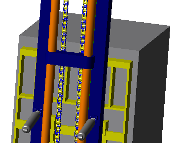
Change rendering mode to Shade.
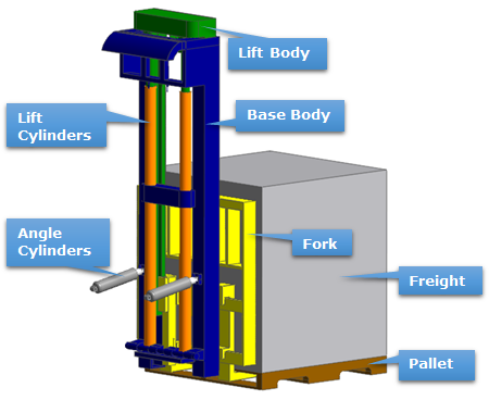
Your model should look like the following: Note that for simplicity the Lift Cylinders and Base Body are combined into a single rigid body. Similarly, the Fork, Freight, and Pallet are rigidly connected with fixed joints. The interested user could remove these fixed joints and replace them with a more realistic contact model if desired. This model is currently missing the chain which we will create next.
9.2.2.3.2. To save the initial model:
From the File menu, click Save As.
Save the model different directory, because you cannot simulation in tutorial directory.
9.2.2.4. Creating the Chain Subsystem
In this section, you create the Chain Subsystem including the Roller Links and a Roller. The chain ends are temporarily attached to ground using elastic joints (bushings). Once you import the chain into the forklift model, you will move the chain end attachments to the appropriate forklift bodies.
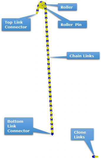
The chain you are about to create is shown in the figure.
9.2.2.4.1. To create the Subsystem:
- From the Subsystem Toolkit group in the Toolkit tab, click the Chain function.The geometry at the model level disappears and you are in an empty Chain subsystem within the model hierarchy.
Next you will create the attachment bodies at the ends of the chain.
9.2.2.4.2. To create the top link attachment body:
From the Body group in the Professional tab, click the Cylinder function.
Set the Creation Method to Point, Point, Radius.
Enter the following values in the Input Window Toolbar:
Point: 8, 1850, -13.75
Point: 8, 1850, 13.75
Radius: 9.54
Right-click the newly created body and select Properties.
Under the Graphic Property page, change the color to Blue (Hex={00,00,FF}).
In the Properties dialog box, click on the General page and rename the body Link_Connector_T.
Click OK to save the changes and exit the Properties dialog box.
9.2.2.4.3. To create the bottom link attachment body:
From the Body group in the Professional tab, click the Ellipsoid function.
Using the Point, Distance creation method, enter 210, 200, 0 and then 10 at the user input bar.
Change the color to blue and rename the body Link_Connector_B.
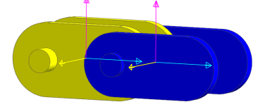
Your model should now look like the following figure.
Next, we will create the Roller and a roller pin which we will fix to ground. We will also define the contact parameters for the Roller which will define its interaction with the chain.
9.2.2.4.4. To create the Roller:
From the Roller group in the Chain tab, click the Roller function.
Using the default Point, Distance creation method, enter 85, 1970, 0 as the center of the Roller and 30 as the roller radius.
Right-click on the Roller and select Properties.
Change the name to Roller in the General page and the color to yellow in the Graphic Property page. On the Contact Characteristic page, define the Stiffness Coefficient as 3160, the Damping Coefficient as 0.75, and the Friction Coefficient as 0.075.
Lastly, set the following values on the Characteristics page:
Roller Width: 45
Total Width: 48
Flange Radius: 55
The Properties dialog box should now look like the following.
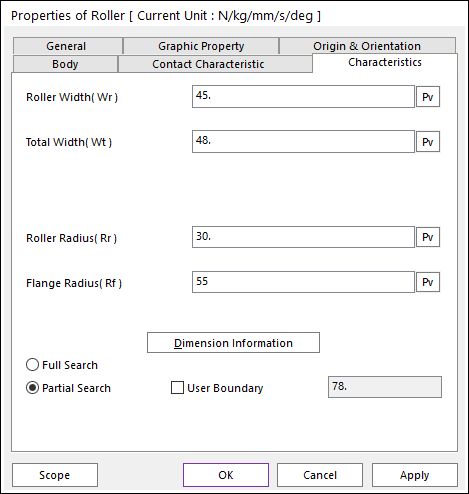
Select OK to accept changes and exit.
9.2.2.4.5. To create the roller pin:
From the Body group in the Professional tab, click the Cylinder function.
Change the Creation Method to Point, Point, Radius and enter the following:
Point: 85, 1970, -25
Point: 85, 1970, 25
Radius: 7
Rename the cylinder Roller_Pin and change the color to green.
Next, we will create fixed joints to temporarily connect the attachment bodies and Roller_Pin to ground. We will also connect the Roller to the Roller_Pin with a bushing.
9.2.2.4.6. To create the fixed joints:
Turn on the Auto Operation function by either pressing A key on your keyboard or clicking on the Auto Operation tool in Advanced Toolbar.
From the Joint group in the Professional tab, select the Fixed Joint function.
Using the Body, Body, Point method create fixed joints in the following locations between the following bodies:
First (Base) Body
Second (Action) Body
Location
MotherBody*
Link_Connector_T
5, 1850, 0
MotherBody*
Link_Connector_B
210, 200, 0
MotherBody*
Roller_Pin
85, 1970, 0
To select MotherBody click anywhere on the Working model window that is not on a body. At the assembly mode this would select Ground but in a Subsystem, it selects MotherBody which is the local (Subsystem edit mode) equivalent to Ground.
After creating the three joints be sure to press A key on your keyboard to turn off Auto Operation mode, and then press Esc key as well to cancel the creation of an extra undesired joint.
9.2.2.4.7. To create the bushing:
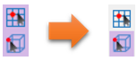
Clicking on the Icon Control tool in Render Toolbar.
Check the all of the check boxes.
Close the dialog.
From the Force in the Professional tab, click the Bushing Force function.
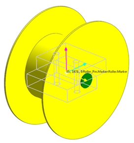
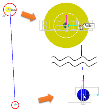
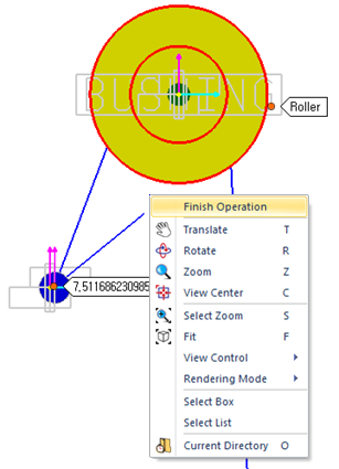
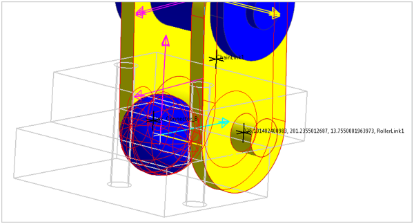
As seen in the following figure, zoom in on the Roller and select the marker at the center of the Roller. With your mouse hovering over this point you should verify that the bushing will be created at the point 85, 1970, 0 with markers being created on the Roller and the Roller_Pin. If this is not the case then change the creation method to Body, Body, Point and make it so.
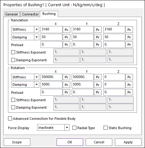
In the Properties dialog box for this bushing rename it B_Roller_Pin and change the stiffness parameters to the following (also shown in the following figure):
Translational Stiffness (X, Y, and Z): 3160
Translational Damping (X, Y, and Z): 50
Rotational Stiffness (X and Y): Leave at default values
Rotational Stiffness (Z): 0
Rotational Damping (X and Y): Leave at default values
Rotational Damping (Z): 0
You will now create the chain itself, first by defining the Roller Link and then by assembling the chain system.
9.2.2.4.8. To define the Roller Link:
From the Link group in the Chain tab, click the Roller function.
Select any point on the Working model window as the location where these link clones will be created. A point such as 800, -100, 0 would be suitable, to simply to keep the links out of the way but not so far as to make the view distorted when fitting the model to the screen using the F key. The links that you create in this step will be used to construct the entire chain.
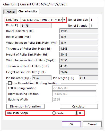
In the dialog box that appears, select ISO 606: 20A, Pitch = 31.75 from the Link Type drop-down menu. This will automatically fill in the appropriate dimensions for the links.
Set Link Plate Shape to Box.
Select OK to save and exit the dialog.
- Change the color of the links to blue and yellow by right-clicking on them one at a time and selecting Properties from the menu.When you are complete the links should look like the following.
9.2.2.4.9. To create the Chain Assembly:
Zoom in on the bottom link connector (Link_Connector_B) by pressing the S key on your keyboard and drawing a box around the body.
Make sure that Snap to Grid is turned off by clicking on the icon shown below if it is highlighted.
From the Assembly group in the Chain tab, click the Assembly function.
Click around the center of the Link_Connector_B body.
Zoom out to viewing the entire subsystem by pressing the F key.
Click on the upper right side of the Roller as shown at below, verifying that the line goes from the center of Link_Connector_B to the right side of the Roller.
Without left-clicking on anything else yet, zoom in on Link_Connector_T by pressing S key and then drawing a box around the body.
Now click around the center of the Link_Connector_T cylinder.
Finish the operation by moving your cursor off to the side but still in the Working model window, right-clicking, and selecting Finish Operation.
A dialog box will pop up after clicking on Finish Operation. In this menu we will define the number of links and Bushing Type. The Working model window shows that the end of the link does not line up directly with the cylinder we created. This is not a problem and will be taken care of in the next section. The only reason this happens is that we are creating an open chain. A closed chain is automatically created to line up the first and last links correctly.
Change the Bushing Type to Single and the Number of Links to 64.
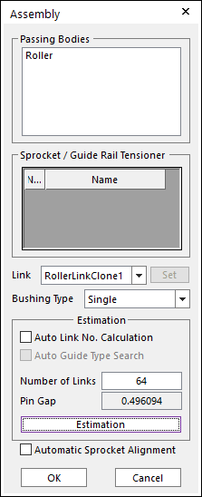
If you click Estimation the Pin Gap field will be updated. This can be used to calculate the number of links you need in order to obtain a desired pretension in the chain by multiplying this Pin Gap by the stiffness that will be used for the chain.
Click OK to finalize the creation of the Chain Assembly.
Now you will create revolute connectors between the chain ends and the Link_Connector bodies. You will also define the stiffness and damping of the connectors and the chain.
9.2.2.4.10. To create the top revolute connector:
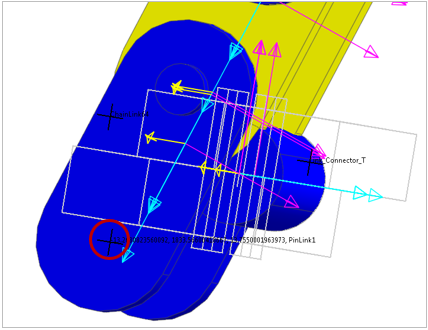
From the Connector group in the Chain tab, click the Revolute Connector function.
Using the Body, Body, Point creation method click first on Link_Connector_T and then on the last link in the chain. For the point, click on the circular center of the link, as shown below. This will snap the bushing creation point to the center of the circular arc on the outside edge of the link end.
Right-click the newly created Connector and select Properties.
Change the Translational Stiffness and Damping to 10000 and 10 respectively. Change the Rotational Stiffness and Damping to 10000 and 500 respectively.
Rename the joint name Rev_Link_Connector_T on the General page.
On the Connector page change the Base Marker Origin to 5, 1850, 0 (the center of Link_Connector_T) and the Action Marker Origin to 15.875, 0, 0 (shifting the link’s marker to the center plane rof the link). The dialog box should look like the following.
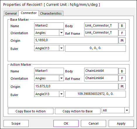
Select OK to save and exit the dialog.
The link end should now look like the following.
9.2.2.4.11. To create the bottom revolute connector:
Just like with the top connector, select the Revolute Connector function of the Connector group in the Chain tab.
First select Link_Connector_B, then select the bottom chain link, then click on the bottom-most circular center of the link. This will cause the joint location to snap to the center of the circular arc as before.
Right-click on the connector and change the stiffness values to match the previous ones. Rename the connector Rev_Link_Connector_B.
Lastly, move the Base Marker Origin to 210, 200, 0 and the Action Marker Origin to -15.875, 0, 0 and select OK to finish.
9.2.2.4.12. To adjust the stiffness and damping of the chain:
Right-click on ChainAssembly1 in the Database window on the right-hand side of the screen. Select Properties and then click Bushing Force to enter the Pin Bushing dialog box for the Chain Assembly.
Change the Translational Damping Coefficient (both Radial and Axial) to 10 while leaving the Stiffness Coefficient at its default value of 10000, as shown at below.
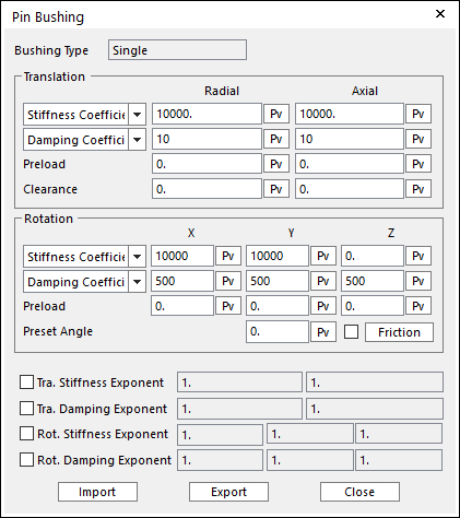
Change the Rotational Stiffness and Damping Coefficients to 10000 and 500 respectively in the X and Y direction. In the Z direction make the Rotational Stiffness and Damping Coefficients to 0 and 500 respectively.
Click Close and then OK to exit and save the settings for the chain.
9.2.2.5. Simulate and Extract the Model
You are now ready to simulate the model, bringing the chain ends into alignment with their connectors. You will finish this chapter by extracting the model in this new orientation. In the next chapter you will connect the chain subsystem to the forklift and simulate the entire system.
9.2.2.5.1. To simulate the model:
Without exiting the subsystem edit mode, select the Dynamic / Kinematic Analysis function of the Simulation Type group in the Analysis tab.
Run the simulation with the following parameters.
End Time: 3
Step: 300
Plot Multiplier Step Factor: 10
This is done at the subsystem mode so that only the subsystem is allowed to change. In keeping with our goal of aligning the chain ends we do not want the bodies at the main system level to move during the simulation or else the Link_Connector bodies would not line up correctly with their attachment points at the main level.
The simulation takes just under three minutes on a PC with a 3.4 GHz Intel Pentium 4 processor and 2.5 GBs of RAM.
View the simulation results by clicking the Play / Pause function. You may want to zoom in on the chain ends to verify that indeed the link ends snap into the correct locations.
At the end of the simulation there is a small amount of chain oscillation remaining. This is not a problem and we will extract the model
9.2.2.5.2. To extract the model:
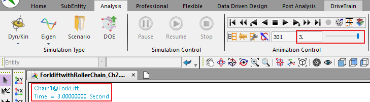
Make sure that you are viewing the last frame of the animation. This can be verified by the 301 (frame number) and 3 (animation time) in the top right corner of the RecurDyn window, as shown below, or by the Time = 3. Second shown in the top left of the Working model window.
From the File menu, select Extract.
Save the extracted model as ForkLift_Step1_Extracted.rdyn.
In the extracted the model, RecurDyn has set the time equal to the time at which the model was extracted (3 sec.). For some models with time-based expressions, this makes it easier to continue with the modeling process after an extract has been performed. For this model, however, you want to reset this value to zero, because the time-based expressions all assume a starting time of zero.
9.2.2.5.3. To reset the model’s time offset:
Select the Simulation Setting function of the Setting group in the Home tab.
For Time Offset, reset the value to 0, as shown at below.
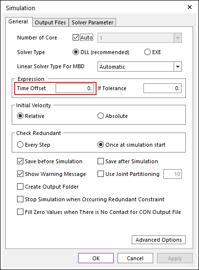
Click OK to accept the change.
9.2.3. Assembling the Forklift
9.2.3.1. Task Objective
Make a copy of the chain subsystem created in the previous chapter and assemble it with the forklift model. Simulate the model and plot the results.
9.2.3.2. Estimated Time to Complete
25 minutes
9.2.3.3. Finish the Chain Subsystem
In this section, you will finish preparing the chain subsystem for integration with the forklift model. This includes moving the clone links, deactivating the fixed joints, and defining which chain links to include in the saved data when simulating.
9.2.3.3.1. To move the clone links:
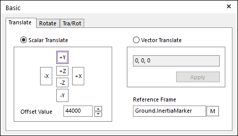
Press the F key on your keyboard to fit the entire model to your screen. Notice that this zooms out far enough to include the clone links in the view. They fell under gravitational acceleration during the previous simulation.
Select them by drawing a box around them (you may have to use the Select Zoom tool to view them). Then open the Basic Object Control dialog box and move them in the +Y direction by 44000 mm.
The fixed joints created in the previous chapter were used to constrain the Link_Connector bodies while aligning the chain ends. They are no longer needed, and you will now deactivate them. Later in this chapter you will create joints at the assembly mode between these connector bodies and the appropriate bodies on the forklift.
9.2.3.3.2. To deactivate the fixed joints:
Select all three fixed joints by clicking on the top one and then, while holding down the Shift key, clicking on the bottom one. With all three highlighted you can now right-click on one of them and select Properties. This allows you to modify all three joints simultaneously.
On the General page, click on the box next to Inactive Flag. A checkmark will appear indicating that the joints will be inactive in the future.
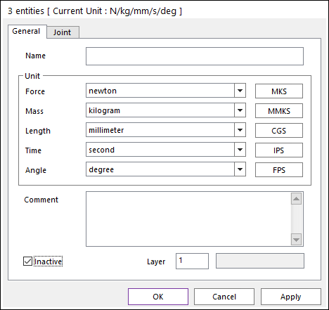
Select OK to save and exit.
Now we desire to set up the output for our Chain Assembly so that we can view the forces and motion for selected links. This will enable us to plot these values after simulating the forklift model. As many or as few links as desired could be included in the output. For simplicity we will choose just 6 of them evenly distributed along the length of the chain.
9.2.3.3.3. To specify desired output links:
Right-click ChainAssembly1 in the Database window and choose Properties.
Go to the Output tab and then click Selection by Simple Rule.
Set the Start Index as 8, the Increment as 8, and the Number of Selections as 7.
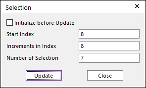
Click Update and then OK to save and exit.
9.2.3.4. Copy and Connect the Chain to the Forklift
We are now ready to move to the assembly mode and assemble the chain system to the forklift model. First, we will need to create a copy of the chain subsystem we created. Then we will create the necessary joints and simulate the model.
9.2.3.4.1. To copy the Chain Subsystem:
Have a Right-Click on the working window and choose Exit to navigate to the assembly mode.
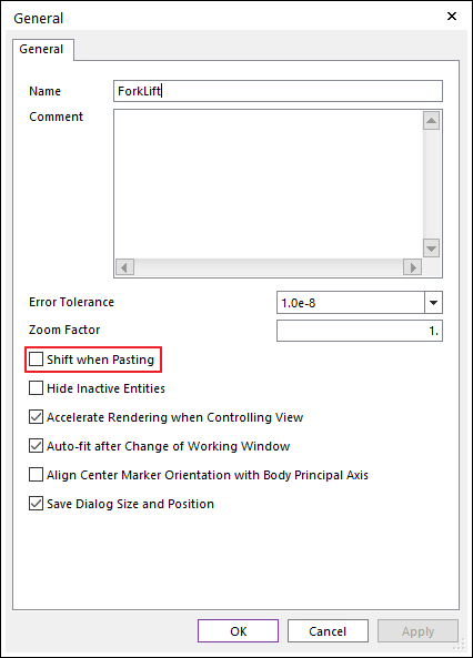
In the Home tab, click the General Setting function of the Setting group.
In the Advanced page, Uncheck the box next to Shift when Pasting.
In the Database window, click on Chain1, press Ctrl+C key to copy it, and then Ctrl+V key to paste it into the same model. You will now have two identical chain subsystems, one right on top of the other, at the center of your model.
Next, we will move these subsystems into the correct locations, rename them, and create the necessary joints.
9.2.3.4.2. To move and rename the subsystems:
In the Database window, select Chain1. Then open the Basic Object Control dialog box and move it 80 mm in the -Z direction.
Repeat the step above with the other chain subsystem, C1_Chain1, but this time moving it 80 mm in the +Z direction instead.
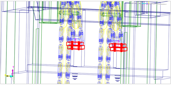
The two chain subsystems should now be in parallel as shown below.
Rename the Chain1 subsystem to Chain_L and C1_Chain1 to Chain_R by right-clicking their entries one at a time in the Database Window, selecting Properties, and then selecting the General page and editing the Name field.
You will begin creating joints at the bottom of the chains and then proceed to the top end and then the roller. Each of the joints created will be a fixed joint connecting the appropriate forklift body to the connector bodies created at the subsystem level.
9.2.3.4.3. To create the bottom fixed joints:
Zoom in on the lower ends of the chains and change the viewing mode to Wireframe with Silhouettes.
Select the Professional tab.
From the Joint group, click the Fixed Joint function.
Using the previously specified Body, Body, Point creation method, select first the yellow Fork body. Then hold the Shift key and select the blue sphere named Link_Connector_B in the left chain subsystem. Finally, click at the center of the sphere to create the joint at that location, as shown below.
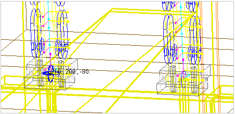
Tip
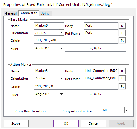
Selecting entities that reside in a subsystem from the main system levelTo select an element of a subsystem from the system level you simply hold down the Shift key. This will enable you to view entities of the subsystem as well as click on them to select them.You should verify that, as shown at right, the Fork is specified as the Base Body, Link_Connector_B@Chain_L is the Action body, and 210, 200, -80 is the Base Marker Origin. The Action Marker Origin should be 210, 200, 0, since that is where the marker is located in the chain subsystem’s local coordinate system.
Repeat the procedure for the right side. This time your joint should be located at 210, 200, 80 and the Action Body should be Link_Connector_B@Chain_R.
Rename the fixed joints Fixed_Fork_Link_L and Fixed_Fork_Link_R, respectively.
9.2.3.4.4. To create the top fixed joints:
Zoom in on the top ends of the chains.
Rotate the view so that you are looking at the forklift from the front. Make sure that you can see the blue cylinders indicated below.
From the Joint group in the Professional tab, click the Fixed Joint function. Verify that the Body, Body, Point creation method is still active.
Click first on the Base_Body and then, type Link_Connector_T@Chain_L at Input Window Toolbar which is blue cylinder’s name attached to the end of the chain. Then click at the center of the cylinder to create the joint at 5, 1850, -80. As done previously, make Fixed joint for right side at 5, 1850, 80.
The two joints should appear as shown below.
Rename the joints Fixed_Base_Link_L and Fixed_Base_Link_R, respectively.
9.2.3.4.5. To create the fixed joints for the Roller_Pins:
From the Joint group in the Professional tab, click the Fixed Joint function.
Select Lift_Body as the Base body.
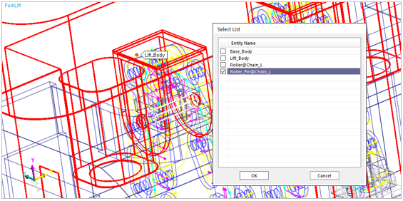
While holding down Shift, hover your mouse over the chain subsystem until its elements appear. Then right-click on the green cylinder (Roller_Pin) and choose Select List from the menu. Check the box next to Roller_Pin@Chain_L to select it as the Action body. Finally, hover your cursor over the center of the cylinder until it snaps to 85, 1970, -80 for the left side or 85,1970,80 for the right. Alternatively, you could enter this point manually into the Input Window Toolbar.
Verify that the fixed joints both have Lift_Body as the Base body and Roller_Pin@Chain_L or Roller_Pin@Chain_R for the Action bodies.
Rename the joints Fixed_Lift_Roller_L and Fixed_Lift_Roller_R respectively.
9.2.3.5. Simulate the Forklift Model
We will now proceed to simulate the forklift model and plot the results. Before running the simulation for a full 3 seconds we will do a test run to verify that the model is assembled and working correctly.
9.2.3.5.1. To simulate the model:
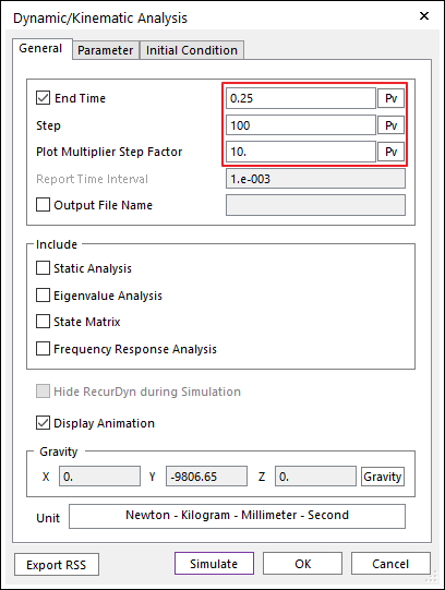
From the Simulation Type in the Analysis tap, click the Dynamic / Kinematic Analysis function.
Run the simulation for 0.25 seconds with 100 Steps and 10 for the Plot Multiplier Step Factor.
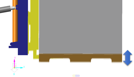
If the model is working properly the freight will start by falling a short distance and then rebound vertically. The simulation will end just as it starts to descend a second time.
Assuming your model has simulated correctly you will now rerun the same simulation for 2 seconds and extract the model in the quasi-equilibrium position. After that you will specify the desired displacements of the hydraulic cylinders and run the simulation again. If time is a factor the 2 second simulation and model extraction can be bypassed. This will affect the beginning of the final simulation by including more transient oscillation, but there will be no significant loss of understanding or functionality of the model.
9.2.3.5.2. To simulate the model:
- Execute the same commands as the previous step but this time simulate for 2 seconds, leaving the Steps and Multiplier at their previous values.The simulation takes just over 6 minutes to complete.
From the Plot group in the Analysis tab, click the Plot Result function.
From the Plot Database Window on the right, navigate to Bodies -> Freight -> Vel_TY. Double-click on Vel_TY to plot the vertical velocity of the freight.
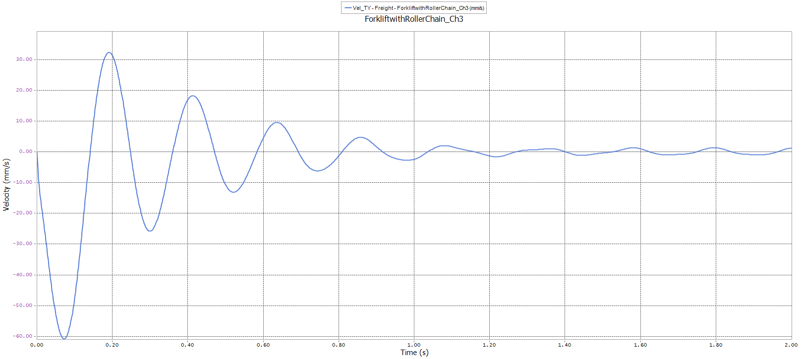
This plot shows that indeed 2 seconds was long enough to bring the system close to its equilibrium position. We will now proceed to extract the model.
9.2.3.5.3. To extract the model:
As was done previously in this tutorial, make sure that you are viewing the last frame of the simulation, and then from the File menu, select the Extract function.
Save the model as Forklift_Step2_Extracted.rdyn or some other meaningful name.
Reset the time offset to zero, as done before.
Next, you will set up the hydraulic cylinders to have the correct motions. First you will apply a lift velocity to the drive cylinders. Then you will apply a displacement to the angle-adjusting cylinders.
9.2.3.5.4. To set the lift velocity:
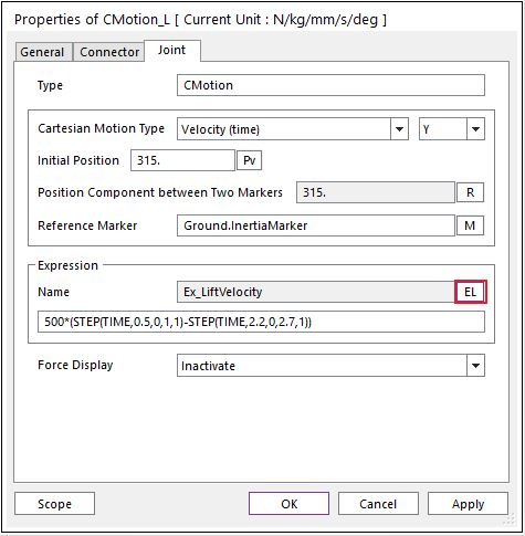
In the Database window, right-click on CMotion_L and then select Properties.
Click EL to choose the new expression that defines the Velocity profile.
Select Ex_LiftVelocity from the Expression List dialog box that appears.
Click OK to accept the new expression and OK again to save and exit the CMotion Properties dialog box.
Perform the same exact steps for CMotion_R to define the same motion for the right drive cylinder.
9.2.3.5.5. To set the angle-adjust displacement:
In the Database window, right-click on Tra_Piston_Cyl_L.
Click Motion to define (or more correctly redefine) the motion for the joint.
In the Motion dialog box which appears, click EL and then select Ex_AngleAdjust from the Expression List.
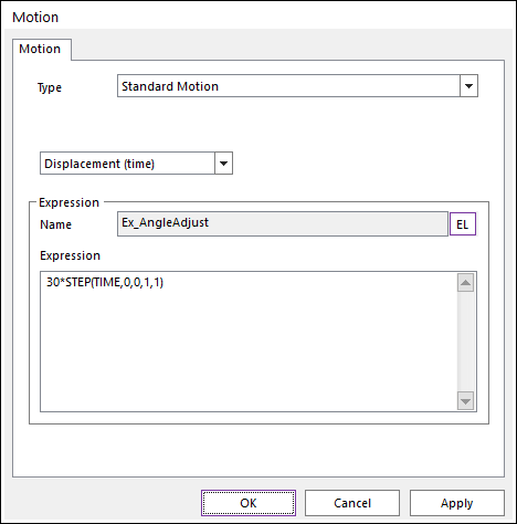
Click OK three times to accept the changes and exit the dialog boxes.
Perform the same steps for Tra_Piston_Cyl_R as well.
Now the model is finally ready to simulate. You will run the simulation for 3 seconds in which the forklift will tilt backwards and then extend the drive cylinders all the way up. A short time is then given to allow the system to come to rest. On a PC with a 3.4 GHz Intel Pentium 4 processor and 2.5 GB of RAM this simulation takes 10 minutes to solve so be sure to plan accordingly.
9.2.3.5.6. To run the final simulation:
Click on the Dynamic / kinematic Analysis function and run the simulation for 3 seconds with 300 Steps and 10 as the Plot Multiplier Step Factor.
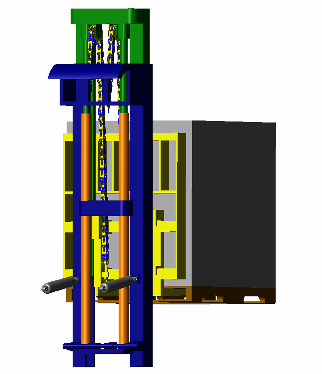
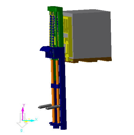
The following figure shows the forklift in its final position.
9.2.3.6. Plot the Results
Finally, you will enter the Plot environment and generate graphs of the freight velocity as well as the forces in some of the bushings and chain links.
9.2.3.6.1. To generate the desired plots:
From the Plot group in the Analysis tab, click the Plot Result function.
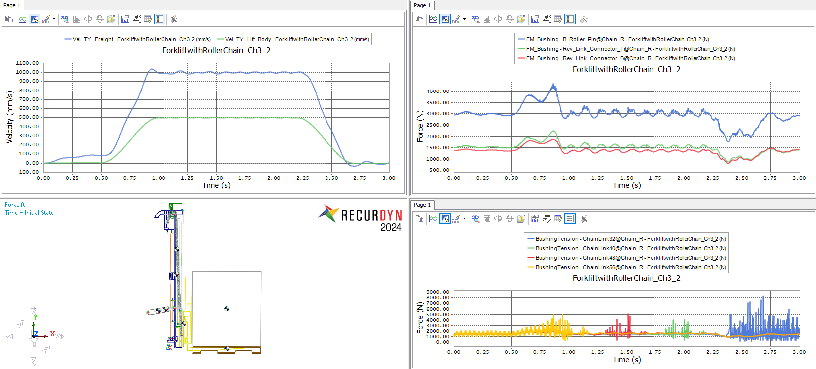
As done previously, double-click on Bodies -> Freight -> Vel_TY.
Then double-click on Bodies -> Lift_Bod* -> Vel_TY to add that trace to the same plot.
This plot shows the effect of the chain on the system. The steady-state value for the Freight while lifting is almost exactly twice that of the lift body as it should be. It also shows the effect of the elasticity in the chains and Roller_Pins.
Change the title of this plot to Freight and Lift_Body Vertical Velocity.
Click the Show All Windows function to see all four panes of the Plot Window.
Click in the top-right pane to activate it.
In this plot, draw bushing force in B_Roller_Pin on the right side of the forklift, by drawing Force -> Bushing Force -> B_Roller_Pin@Chain_R -> FM_Bushing.
Repeat for Rev_Link_Connector_T and Rev_Link_Connector_B.
Rename this plot Bushing Forces in the Chain Connectors.
Click in the lower-right pane to activate it.
In this plot, draw the tension in ChainLink32’s bushing on the right side of the forklift, by drawing Chain-Force -> Link -> ChainLink32@Chain_R -> BushingTension.
Repeat for ChainLink40, ChainLink48, and ChainLink56.
Note
The bushing tension spikes one after another for the consecutive links, starting with the highest numbered one. This is intuitive because the chain started at the bottom and finished at the top, so the highest-numbered links are at the top of the chain. They are consequently the first ones to pass over the roller. The relatively low damping of the roller surface combined with a high contact stiffness and small link mass induces the vibration in the links as they pass over the roller.
Rename the plot Tension in the Chain Links.
Finally, click in the lower-left pane to activate it.
Click the Load Animation function of the Animation group in the Tool tab, to place a screenshot of the forklift model in this pane. Dismiss the warning dialog that displays by selecting Yes, since there is no data in that pane to worry about erasing.
Adjust the image to an acceptable location and angle.
Save the plot if desired by clicking the Save function and choosing a filename.
The plot should appear as shown below.
There are many additional steps that can be taken to explore the behavior of this model and make it more realistic:
One suggestion is to remove the fixed constraint between the Freight and the Fork and replace it with a contact model to explore the effect of the lift velocity profile on the stability of the freight.
A design study could also be performed to explore the effect of chain stiffness and damping on the vibration in the system.
The contact parameters for the Roller could be varied to measure the tradeoff between high-frequency noise and surface deformation.
These are left as optional activities for the interested user.