9.10. Low-mobility Tracked Vehicle Tutorial (Track_LM)
9.10.1. Getting Started
9.10.1.1. Objective
This tutorial introduces you with the Low-Mobility (LM) Track Transport Toolkit and how to simulate the behavior of tracked vehicles on rigid, soil, and snow terrains. You will learn how to define undercarriage components and track shoes. You will also learn how to efficiently define the assembled track that will wrap around the undercarriage components. The tutorial is made up several main chapters, followed by two optional exercises. You can choose to work through any of the optional exercises after creating the model as instructed in main chapters.
The process that you will follow in the tutorial and the process automation tools that you will use to define the LM Track are similar to the processes and tools used to define belt/pulley and chain/sprocket subsystems. Therefore, the concepts that you learn while performing this tutorial will help you learn how to use the belt and chain toolkits more quickly. In addition, if you have already worked through a belt or chain tutorial, you will find this tutorial easier to work through than someone who has no experience with the belt or chain tutorials.
The terms low-mobility and high-mobility refer to two different styles of tracked vehicles. The low mobility toolkit is focused on:
Tracked construction equipment with discrete steel shoes.
Track shoes that are defined as an extruded profile.
External guides that keep the track shoes from falling off of the rollers.
Single sprocket that contacts the shoes at their centers.
The high-mobility toolkit is focused on:
Tracked military vehicles.
Track shoes that are defined as blocks with attached cleats.
Center guides on the track shoes that pass-through grooves in the roadwheels and the idler to keep the track shoes from falling off of the rollers.
Dual sprocket that contacts the shoes at the pins that protrudes from the sides of the track shoe.
The names low-mobility and high-mobility refer to the vehicle’s speed of operation. Typically, construction equipment operates at a slower (or low) speed while the military equipment operates at a fast (or high) speed, especially during transport.
9.10.1.2. Audience
This tutorial is intended for experienced users of RecurDyn
9.10.1.3. Prerequisites
Users should first work through the 3D Crank-Slider Tutorial and the Engine with Propeller Tutorial
9.10.1.4. Procedures
The tutorial is comprised of the following procedures. The estimated time to complete each procedure is shown in the table.
Procedures |
Time (minutes) |
Simulation environment setup |
15 |
Track component definition |
35 |
Track subsystem completion |
15 |
Full-vehicle model development |
15 |
Subsystem tuning(optional) |
20 |
Addition of blade linkage(optional) |
30 |
Total |
130 |
9.10.1.5. Estimated Time to Complete
2 hours
9.10.2. Setting Up the Simulation Environment
In this chapter, you will start RecurDyn and set up its environment, including importing the completed bulldozer chassis with cab. You will also merge the imported geometry into one body and set its center of mass.
9.10.2.1. Task Objective
Learn to set up the RecurDyn environment and import data.
9.10.2.2. Estimated Time to Complete
15 minutes
9.10.2.3. Starting RecurDyn
9.10.2.3.1. To start RecurDyn and create a new model:
On your Desktop, double-click the RecurDyn icon. RecurDyn starts and the Start RecurDyn dialog box appears.
Ensure the units are the same as those shown in the Start RecurDyn dialog box to the right. If not, click MMKS.
Change the model name to LM_Track_Tutorial as shown in the window, and then click OK.
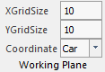
Set the grid spacing to 10 mm.
9.10.2.4. Importing the Chassis Geometry
You will begin to model the tracked vehicle by importing an already completed bulldozer chassis.
9.10.2.4.1. To import the chassis geometry:
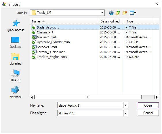
From the File menu, choose the Import function.
- In the Open dialog box, set file type to ParaSolid File, and from the Track LM Files folder, select the file Chassis.x_t as shown in the dialog box on the right.(The file path: <InstallDir>\Help\Tutorial\Toolkit\Track_LM\LowMobilityTrackedVehicle)
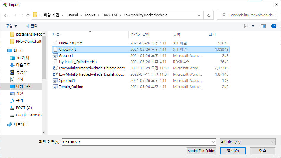
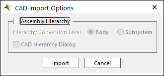
Click Open. The CAD Import Options window appears. Clear the Assembly Hierarchy checkbox and click Import.
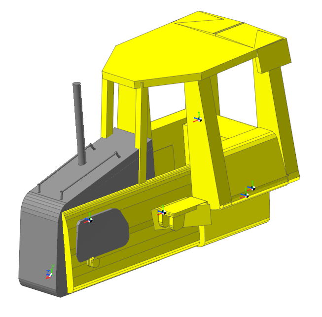
The bulldozer chassis appears as shown below after rotating it and setting the render mode to Shade with wire.
9.10.2.5. Merging the Bodies
The chassis is made up of five bodies. You are going to merge them into one body to make it easier to work with the chassis. In addition, you are going to change the center of mass to reflect the new merged body.
9.10.2.5.1. To merge the bodies:
From the Tools group in the Home tab, click the Merge function.
Select all the bodies in the Merge Body dialog box.
Enter ImportedBody1 as the target body, either by typing the name into the Target Body text box or by clicking B and selecting the cab geometry. The target body is the body into which all the bodies will be merged.
Check the User Input in Material Input option to set the Body Material Type to User Input.
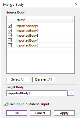
Click OK.
Display the Properties dialog box for the merged body, ImportedBody1 and do the following:
Tip
In the Database Window, right-click ImportedBody1 and click Properties.
Click the General page, if necessary, and change the name of ImportedBody1 to Chassis.
Click Apply.
From the Body page, Click CM and change the Origin to -1400, 500, 0.
Click OK to close the CM dialog box.
Click OK again to close the Chassis Properties dialog box.
Save the RecurDyn model as LM_Track_Tutorial.rdyn.
9.10.3. Defining the Track Components
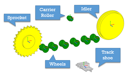
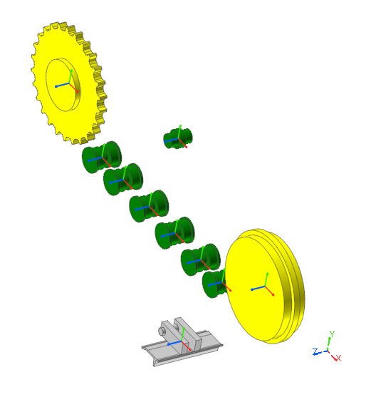
In this chapter, you will define the objects that make up the track using the TrackLMSub1 tools. In the next chapter, you will assemble the objects together. The objects that you will create are shown below
9.10.3.1. Task Objective
Learn to create the objects that define a track and understand the process of creating a track using the Track LM tools.
9.10.3.2. Estimated Time to Complete
35 minutes
9.10.3.3. Defining the Right Track Assembly
You will create a low-mobility track subsystem which then provides you with access to standard entities in the LM Track Transport Toolkit, such as:
Sprockets
Rollers used to define road wheels, idlers, and carrier rollers
Track links, lateral guards for the track, and a terrain builder
9.10.3.3.1. To define a new low-mobility track subsystem:
From the Subsystem Toolkit group in the Toolkit tab, click the Track (LM) function.
After RecurDyn creates the subsystem, it is in Subsystem Edit mode. The name in the upper left of the graphics window is TrackLM1@LM_Track_Tutorial and the top node in the Database Window is TrackLM1.
9.10.3.4. Creating a Track Shoe
You will create a track shoe and define the grouser profile by importing a set of xy data points. You could create the set of points by exporting a profile from your CAD software or by calculating the points in Excel. The points are simply exported as two columns that are separated by a delimiter, such as a comma or a space. You should change the extension of the file name to .mat.
9.10.3.4.1. To create a track shoe:
From the Link group in the Track (LM) tab, click the Link function. (This procedure proceed in the subsystem edit mode named TrackLM1)
Click the location -1400, -900, 0.
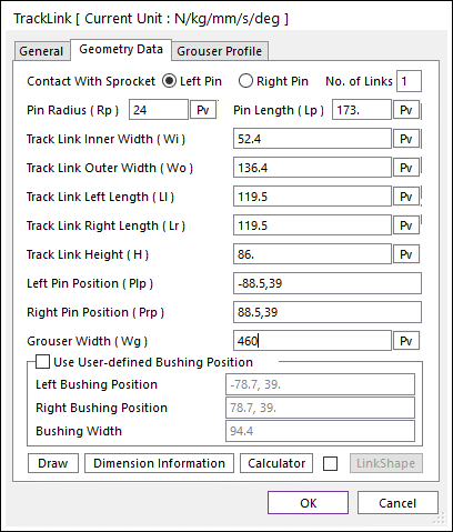
In the TrackLink dialog box, click the Geometry Data page and fill in the text boxes as shown in the dialog box on the below. You will adjust the:
Pin Radius: 24
Track Link Left Length: 119.5
Track Link Right Length: 119.5
Left Pin Position: -88.5, 39
Right Pin Position: 88.5, 39
Grouser Width: 460
To view a graphical description of the geometry data, click Dimension Information.
Keep the TrackLink dialog box open.
9.10.3.4.2. To import a new track link grouser profile:
In the TrackLink dialog box, click the Grouser Profile page, and then click Import.
Select the Grouser1 file (.mat file extension may or may not be visible) from the Track LM Files directory (The file path: <InstallDir>\Help\Tutorial\Toolkit\Track_LM\LowMobilityTrackedVehicle) and click Open.
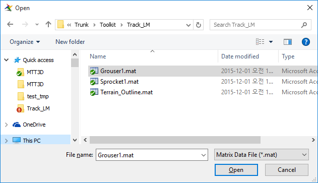
The grouser coordinates appear as shown at the below.
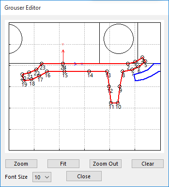
Click Draw to display the grouser profile as shown.
As you review the grouser profile, you will see that nodes (points) 7 through 19 cover the section of the grouser that will contact the terrain. You want those nodes to be included in the contact calculations for hard terrains.
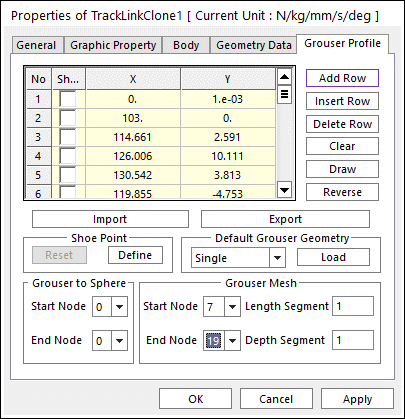
In the spreadsheet of the TrackLink dialog box, check the boxes under the Shoe column for points 8, 10, 12, 14, 16, and 18.
To set up the grouser points, in the Shoe Point section, click Define.
You also want to set up the contact calculations for soft terrains (soils, sands, snow, and so on).
In the TrackLink dialog box, set the Start Node to 7 and the End Node to 19 in the Grouser Mesh section.
Click OK to exit the TrackLink dialog box.
Display the TrackLink1 Properties dialog box and set its color to light gray (Graphic Property page).
Click OK.
9.10.3.5. Creating a Sprocket
9.10.3.5.1. To create a sprocket:
From the Sprocket group in the Track (LM) tab, click the Sprocket function.
Click the location -2900, 0, 0.
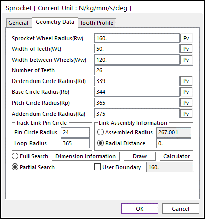
In the Sprocket dialog box, click the Geometry Data page.
Click Dimension Information to see the meaning of the various entries.
Fill in the text boxes as shown in the dialog box on the right. You will adjust the:
Number of Teeth: 26
Dedendum Circle Radius (Rd): 339
Base Circle Radius (Rb): 344
Pitch Circle Radius (Rp): 365
Addendum Circle Radius (Ra): 375
Pin Circle Radius (Rp): 24
Loop Radius: 365 (typically the same as the pitch circle radius)
Keep the dialog box open.
9.10.3.5.2. To import a new sprocket tooth profile:
In the Sprocket dialog box, click the Tooth Profile page, and then click Import.
- Select the sprocket1 file (.mat file extension may or may not be visible) from the Track LM Files directory.(The file path: <InstallDir>\Help\Tutorial\Toolkit\Track_LM\LowMobilityTrackedVehicle)
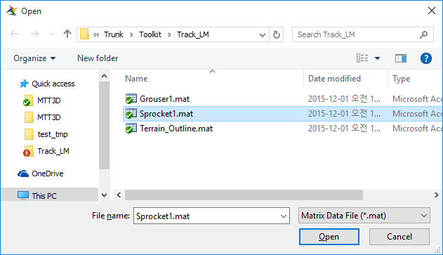
Click Open.
Click OK.
Display the Sprocket Properties dialog box and set the color of the sprocket tooth profile to yellow (Graphic Property page).
Click OK.
9.10.3.6. Creating a Set of Road Wheels
In this section, you will create six road wheels, as shown in the figure on the below. You will set their properties and change their names.
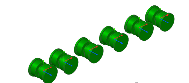
9.10.3.6.1. To create a set of road wheels:
From the Flange group in the Track (LM) tab, click the Single Roller function.
Create six road wheels with centers at the locations specified in the table below. You can create each road wheel individually and modify its properties individually, or you can create one road wheel, modify its properties, make a copy, move it to the correct position and repeat for the six road wheels. If copying, remember to turn off the Shift when Pasting option (see Home Tab -> Setting Group -> Display -> Advanced). In the next step, you will rename the road wheel names as listed in the table.
Set the single flange
To point (X,Y)
With a distance (radius)
X offset (if copying)
Change name to Road Wheel #
SingleFlange1
-2460, -250
70
6
SingleFlange2
-2220, -250
70
240
5
SingleFlange3
-1930, -250
70
290
4
SingleFlange4
-1640, -250
70
290
3
SingleFlange5
-1350, -250
70
290
2
SingleFlange6
-1110, -250
70
240
1
Display the Properties dialog box for each road wheel.
Click the Characteristics page and set the parameters to be the same as in the figure and listed below:
Hub Radius (Rh): 40
Flange Radius (Rf): 80
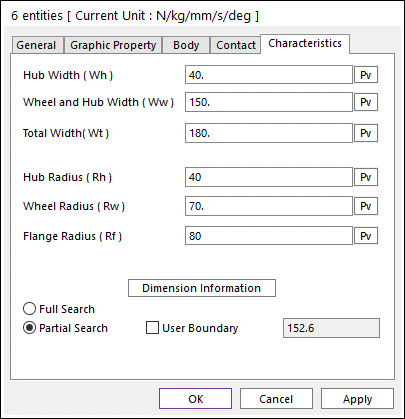
Change their color to green.
Rename them from SingleFlange1 through SingleFlange6 to RoadWheel_6 through RoadWheel_1, renaming them in descending order, as shown in the table above.
9.10.3.7. Creating an Idler
9.10.3.7.1. To create an idler:
From the Flange group in the Track (LM) tab, click the Center Roller function.
Create a flange with a center at -700, 0, 0. and a radius (distance) of 320 (enter it in the Input Window Toolbar or drag the mouse horizontal or vertical until the readout is 320).
Display the CenterFlange1 Properties dialog box to set the color of the idler to yellow (Graphic Property page).
Click the Characteristics page and set Inner Flange Radius (Rf) to 350.
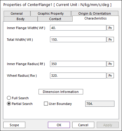
Click the General page and set the name to Idler.
Click OK.
9.10.3.8. Creating a Carrier Roller
9.10.3.8.1. To create a carrier roller:
From the Flange group in the Track (LM) tab, click the Center Roller function.
Create a flange with a center at -1780, 360, 0 and a radius (distance) of 45 (enter it in the Input Window Toolbar).
Display the CenterFlange1 Properties dialog box to set the roller color to green (Graphic Property page).
Click the Characteristics page and set Inner Flange Radius (Rf) to 60.
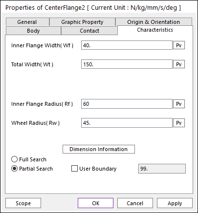
Click the General page and change the name to Carrier.
Click OK.
Your track subsystem should look like the figure below (rotated, and with the render mode set to Shade With Wire).
You are now ready to assemble the track.
9.10.4. Finishing the Track Subsystem
In this chapter, you will complete the modeling of the subsystem by creating the track, creating the track frame geometry and attaching the track components to the track frame. You will add a motion to the sprocket and be prepared to simulate the behavior of the track subsystem.
9.10.4.1. Task Objective
Learn to assemble a track, create a track frame, and attach the track components to the track frame.
9.10.4.2. Estimated Time to Complete
30 minutes
9.10.4.3. Assembling the Track
9.10.4.3.1. To assemble the track:
From the Assembly group in the Track (LM) tab, click the Assembly function.
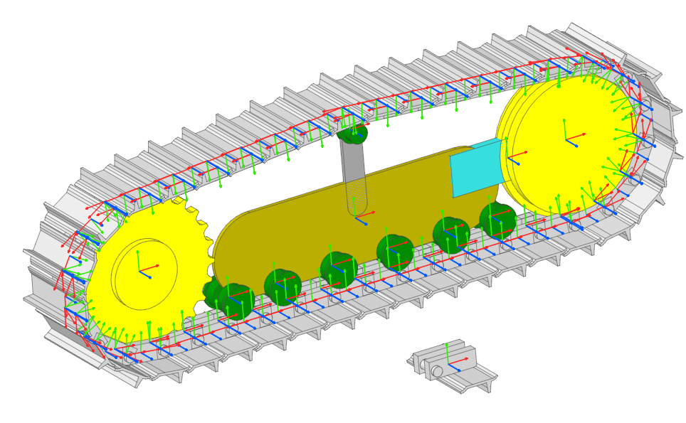
Starting with the sprocket, select each item in the track in a counterclockwise order until you have completed the loop as shown in the figure following.
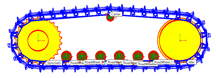
When you are done, a dialog box appears as shown on the below.
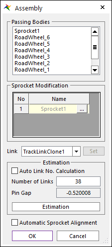
Click OK and RecurDyn adds the components to the database.
9.10.4.4. Creating a Track Frame
9.10.4.4.1. To create a track frame body:
From the Marker and Body group in the Professional tab, click the Link function.
Click the following two points to create the link.
-2325, -80, 0
-1260, -80, 0
9.10.4.5. Editing the Track Frame Body
9.10.4.5.1. To edit the track frame body:
Enter Body Edit Mode for the link body you just created by either.
Double-clicking on the geometry of the body that you just created.
In the Database Window, right-clicking Body1, and selecting Edit.
Display the Properties dialog box for the link geometry and do the following.
Change the First Radius and Second Radius values to 200 and the Depth to 20.
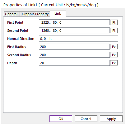
Click OK.
9.10.4.6. Creating the Carrier Holder
9.10.4.6.1. To create the carrier holder:
From the Marker and Geometry group in the Geometry tab, click the Link function.
Click the following two points to create the link.
-1780, 0, 0
-1780, 350, 0
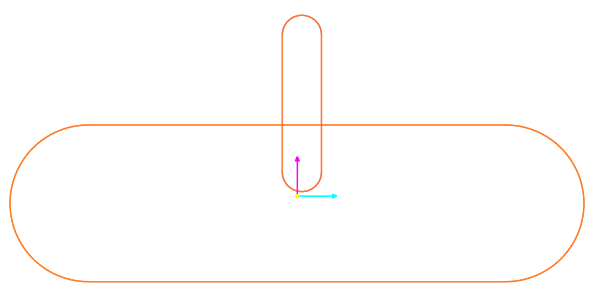
Display the Properties dialog box for the second link geometry and do the following.
Change the First Radius and Second Radius values to 50 and the Depth to 20.
Click OK.
Click the Exit arrow to exit Body Edit mode and return to the subsystem.
Display the Properties dialog box for this body and:
Set the name to Track_Frame.
In the Graphic Property page, change the color to orange.
Click OK.
9.10.4.7. Creating a Tensioner Body
9.10.4.7.1. To create a tensioner body:
From the Marker and Body group in the Professional tab, click the Box function.
Click on the following two points to create the box.
-1300, 100, 0
-700, -100, 0
Double-click the tensioner to enter Body Edit Mode.
Display the Properties dialog box for the tensioner and do the following.
In the Box page, change Depth to 40.
In the Origin & Orientation page, change Origin to (-1000, 0, -20).
Click OK.
Click the Exit function to return to the subsystem edit mode.
Display the Properties dialog box for the tensioner and do the following.
Click the General page, if necessary, and set the name to Tensioner.
Click the Graphic Property page and change the color to Aqua.
Click OK.
The track assembly now appears as shown in the figure on the below.
9.10.4.8. Creating Joints
In this section, you will create a series of revolute and fixed joints to properly attach the sprocket, road wheels, idler, and carrier to the track frame to the Mother Body (local ground in subsystem).
9.10.4.8.1. To create joints:
Using the tools of the Joint group in the Professional tab, create the following joints as specified in the table below. Use the Body, Body, Point option for joints located away from the body geometry.
Create the joint of type |
First Body |
Second Body |
At the location |
Revolute |
Sprocket1 |
MotherBody |
-2900, 0, 0 |
Revolute |
Idler |
Tensioner |
-700, 0, 0 |
Revolute |
RoadWheel_6 |
Track_Frame |
-2460, -250, 0 |
Revolute |
RoadWheel_5 |
Track_Frame |
-2220, -250, 0 |
Revolute |
RoadWheel_4 |
Track_Frame |
-1930, -250, 0 |
Revolute |
RoadWheel_3 |
Track_Frame |
-1640, -250, 0 |
Revolute |
RoadWheel_2 |
Track_Frame |
-1350, -250,0 |
Revolute |
RoadWheel_1 |
Track_Frame |
-1110, -250,0 |
Revolute |
Carrier |
Track_Frame |
-1780, 360,0 |
Fixed |
Tensioner |
Track_Frame |
-1200, 0, 0 |
Fixed |
Track_Frame |
Mother Body |
-1780, 0, 0 |
9.10.4.9. Adding a Motion Input
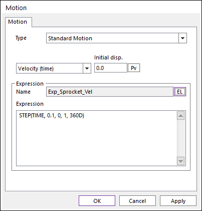
In this section, you are going to add a motion input to the revolute joint of the sprocket that smoothly brings the sprocket velocity up to one revolution per second (360 degrees per second). The velocity will begin to ramp up at 0.1 seconds and will be fully developed at 1.0 second.
9.10.4.9.1. To add a motion input:
Right-click the revolute joint at the center of the sprocket (RevJoint1) and click Properties.
Check the Include Motion check box.
Click Motion.
Set the unlabeled pull-down menu to Velocity.
Click EL to view the Expression List.
Click Create to create an expression.
Change the expression name to Exp_Sprocket_Vel, and define the expression as:
STEP(TIME, 0.1, 0, 1, 360D)
Click OK four times to exit all the way out of the Joint Properties dialog box.
9.10.4.10. Validating the Track Subsystem Definition
In this section, you will run a simulation to validate the subsystem. The track system is fixed in space and there is no terrain for the track to contact. You will be able to see the sprocket motion and the motion of the track over the road wheels, idler, and carrier.
9.10.4.10.1. To validate the subsystem:
Run a simulation for 5 seconds and 250 steps.
View the animation by using the animation control buttons.
Select the Exit function to go to the assembly mode.
9.10.5. Developing and Running the Full-vehicle Model
In this chapter, you will develop a full-vehicle model by making a copy of the completed track system and attaching both track subsystems to the chassis. You will build a terrain and then run the tracked vehicle over the terrain.
9.10.5.1. Task Objective
Learn to combine two subsystems with other geometry at the main model level and how to define a terrain.
9.10.5.2. Estimated Time to Complete
30 minutes
9.10.5.3. Adjusting the Subsystem Properties
There are two subsystem properties that you must adjust at the model level:
Change the name of the subsystem to make it easier to identify.
Define the mapping so the Mother Body in the subsystem corresponds to the Chassis body at the Model level. This mapping is very useful because it helps you simulate the subsystem in a fixed position (attached to the Mother Body) while also properly attaching the subsystem to the Chassis when you simulate at the Model level.
9.10.5.3.1. To adjust the subsystem properties:
Display the Properties dialog box for TrackLM1 subsystem.
Click the General page and change the name of the subsystem to Right_Track_Assy.
Display the Properties dialog box for the track subsystem.
In the Subsystem page, change the Mother Body to the Chassis body.
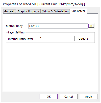
Click OK.
9.10.5.4. Positioning and Testing the Right Track Assembly
You will move the right track subsystem into position with respect to the chassis.
9.10.5.4.1. To position the subsystem:
Select the Right_Track_Assy subsystem, and display the Basic Object Control dialog box to move the subsystem:
Enter 250 mm in the Offset Value text box and click +X.
Enter 300 mm in the Offset Value text box and click -Y.
Enter 1000 mm in the Offset Value text box and click +Z.
9.10.5.4.2. To test the subsystem:
Add a fixed joint between the chassis and ground to hold up the chassis for this test. The location of three fixed joint does not matter.
Run a simulation for 5 seconds and 250 steps and compare the results to the previous animation.
9.10.5.5. Creating the Left Track Subsystem
You will create the left track subsystem by making a copy of the existing track subsystem and by moving the new track subsystem to the other side of the chassis. You will then test this step.
9.10.5.5.1. To create the left track subsystem:
From the Setting group in the Home tab, click the General Setting function.
If needed, clear the selection of the box next to Shift when Pasting (you may have already cleared this box when you were creating the road wheels).
Click OK to exit the General Settings dialog box.
Select the right track subsystem, copy it, and paste it (this will take a few seconds).
Display the Properties dialog box for the new track assembly and do the following:
Click the General page, if necessary, and change the name to Left_Track_Assy.
Click the Origin & Orientation page, and change Origin to (250, -300, -1000).
Click the Subsystem page, and change Mother Body to Chassis.
Click OK.
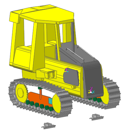
Your model should appear as shown on the below.
9.10.5.5.2. To test the subsystem:
Run a simulation for 5 seconds and 250 steps and compare the results to the previous animation.
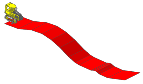
9.10.5.6. Defining a Terrain
Edit the ground body and define a terrain.
9.10.5.6.1. To define the terrain:
To enter the ground edit mode, click the Ground function of the Marker and Body group in the Professional tab.
Click the Outline function of the Curve group in the Ground tab.
Create an outline by using the data in the table to the below.
No.
X
Y
1
-3,500
-1,600
2
250
-1,350
3
3,700
-250
4
6,500
0
5
9,050
-450
6
11,450
-1,350
7
13,950
-2,600
8
15,750
-3,250
9
16,850
-3,400
10
20,100
-3,400
11
20,500
-3,250
12
21,050
-3,100
13
21,450
-3,100
14
21,850
-3,250
15
22,350
-3,400
16
24,600
-3,400
17
29,200
-2,100
When you finish selecting the points, right-click and click Finish Operation.
Tip
Another option is for you to create a dummy outline and import the coordinates from the file Terrain_Outline:
Create an outline with two points that are anywhere on the screen. Right-click and select Finish Operation.
Right-click the outline and select Properties.
- Click Import and select the file Terrain_Outline.mat.(The file path: <InstallDir>\Help\Tutorials\Toolkit\Track_LM\LowMobilityTrackedVehicle)
Make a copy of the outline (copy and paste) and move the outline 2500 mm in the +z direction and the first outline 2500 mm in the –z directions.
To create a terrain (road surface), click the Spline Road function of the Road Data group in the Ground tab.
Click the near outline, then the far outline, then right-click and click Finish Operation.
RecurDyn creates the road data entity.
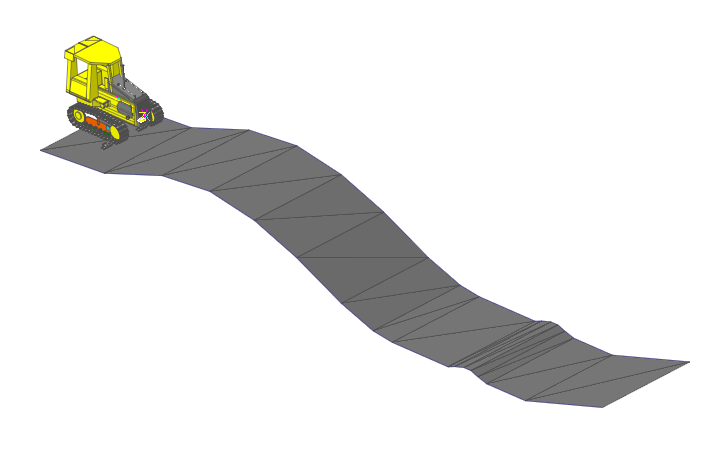
Select the Exit arrow to return to the assembly mode.
The result is shown in the below figure.
9.10.5.6.2. To test the full-vehicle model with the terrain:
In the Database Window, expand Joints, and right-click the name of the fixed joint (between the chassis and ground) that appears and select Inactive to make the joint inactive.
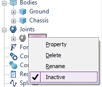
The joint icon in the Database Window and in the graphics window turns gray. You are making the fixed joint inactive to allow the bulldozer to drop down and make contact with the terrain.
Run a simulation for 5 seconds and 250 steps and compare the results to the previous animation.
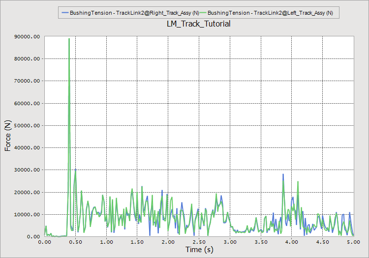
Display the Plot window and plot the tension in the tracks by expanding the Track-Force, expanding each track link entity and double-clicking Bushing Tension.
If you have the time, run the simulation again, but this time for 12 seconds and 600 steps. You will see that the bulldozer will traverse much of the terrain.
Save the RecurDyn model.
The remaining sections of the tutorial contain optional exercises.
9.10.6. Track Subsystem Tuning (Optional)
In this chapter, you will consider a variety of topics related to the detailed modeling of tracked vehicles. In the earlier chapters of this tutorial, you accepted many default values as you created the track components and the track assembly. Here you will find out how to modify some interesting track system values.
9.10.6.1. Task Objective
Learn to work with the various value and parameters associated with the track assembly and the track components. As you use the LM Track toolkit to model your own products, you will adjust these parameters according to your engineering and test data to develop validated models.
9.10.6.2. Estimated Time to Complete
20 minutes
9.10.6.3. Adjusting the Track Assembly Parameters
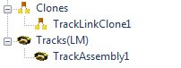
When you execute the Track Assembly operation, RecurDyn creates a Track Assembly entity. It appears near the bottom of the Database Window as shown in the figure on the below. Right-click the Track Assembly entity and click Properties to display its Properties dialog box. It contains several tabs, which are explained in the next sections.
9.10.6.3.1. General Page:
Use the General page to modify the Name of the Track Assembly.
9.10.6.3.2. Characteristics 1 Page:
Use the following options:
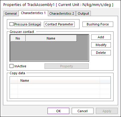
Set track stiffness by clicking the Bushing Force.
Set the translational and rotational stiffness and damping values for all degrees of freedom for the two bushings used to connect each track link to the next.
Set the track tension by setting a preload in the Radial direction of the bushing force.
Define the interaction between the track and a soft soil (clays, sands, loams, even snow) by selecting Pressure-Sinkage and then clicking Contact Parameter. You can select the soil type from the select list and click Load to load the Bekker parameters for that soil. You can modify the parameters and save them to a file to create your own library of soils.
9.10.6.3.3. Characteristics 2 Page:
The Characteristics 2 page is used to define or modify the list of entities that the track contacts.
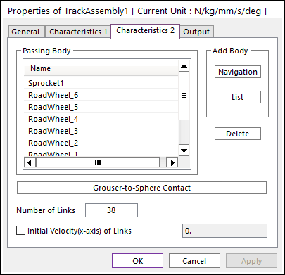
If you want to add another carrier roller, you will create the new roller and then use Navigation (for clicking from the graphics screen) or List to select the new roller from a list.
Use Grouser-to-Sphere Contact to select spheres that have been defined to represent rocks in the terrain or any other supplemental contact with the track.
Set the Initial Velocity of the track by checking Initial Velocity (x-axis) of Links box at the bottom of the dialog box and entering the desired initial velocity in the text box.
9.10.6.3.4. Output Page:
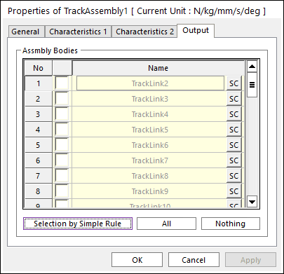
You can use the Output page to customize which track links have their outputs saved from the simulation. The default is to save only the data from the first link, TrackLink2. You can manually check the boxes or use Selection by Simple Rule to automate the selection of links according to a numbering increment.
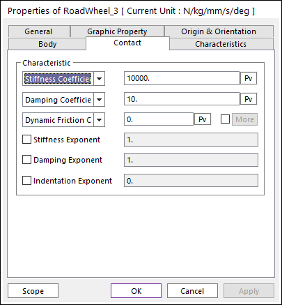
9.10.6.4. Adjusting the Track Component Parameters
9.10.6.4.1. Contact between components and the track:
The contact characteristics between any track wheel or sprocket to the track assembly can be different. For that reason, the contact parameters are set in the Contact Characteristic page of each component. You can set the stiffness, damping, and friction according to the materials used in each component and the state of the component (that is, according to wear).
9.10.6.5. Setting Up a Mechanical Track Tensioner
To create a mechanical track tensioner, do the following for each track subsystem.
9.10.6.5.1. Replace the Fixed joint with a Translational joint:
Enter the Right_Track_Assy subsystem edit mode. (if necessary)
Delete the Fixed joint between the Track_Frame and the Tensioner by selecting the name Fixed1 in the Joints section of the Database Window, clicking the right mouse button with the cursor still over the name, and selecting the Delete option in the menu that pops up.
Create a Translational joint between the Track_Frame and the Tensioner by selecting the Translate Joint function of the Joint group in Home the tab and selecting Body, Body, Point, Direction input method.
Body1: Track_Frame
Body2: Tensioner
Joint Origin Point: -1200, 0, 0 (Use markers remaining from Fixed joint)
Position Vector: Tensioner.Box1 (1,0,0) (Select the horizontal edge on the top of the Tensioner body or select the edge using the Flip List to orient the joint to be horizontal)
9.10.6.5.2. Add a Tensioning Spring
Add a Spring (of the Force group in the Professional tab) between the Track_Frame and the Tensioner (you can select the locations of the ends of the spring).
Body1: Track_Frame
Body2: Tensioner
Point 1: -1500, 0, 0 (on the Track_Frame)
Point 2: -1200, 0, 0 (on the Tensioner)
Bring up the Properties of the Tensioner Spring by placing the cursor over the Spring1 in the Force group of the Database Window, clicking the right mouse button, and selecting the Properties option.
Under the Spring page, set the parameters listed below. The spring is set to a low stiffness value so that the spring force remains close to a constant value as the Tensioner stretches the track.
Stiffness Coefficient: 0.1
Damping Coefficient: 100
Pre Load: 50000
Under the Graphic page, set the Spring Diameter to 50.
Click OK to exit the Properties dialog box.
9.10.6.5.3. Validate the Track Tensioner
Run a simulation for 5 seconds, 250 Steps, and with the Plot Multiplier set to 8.
Play back the animation and you will see that the idler stretches forward by a small amount in response to the track tensioner.
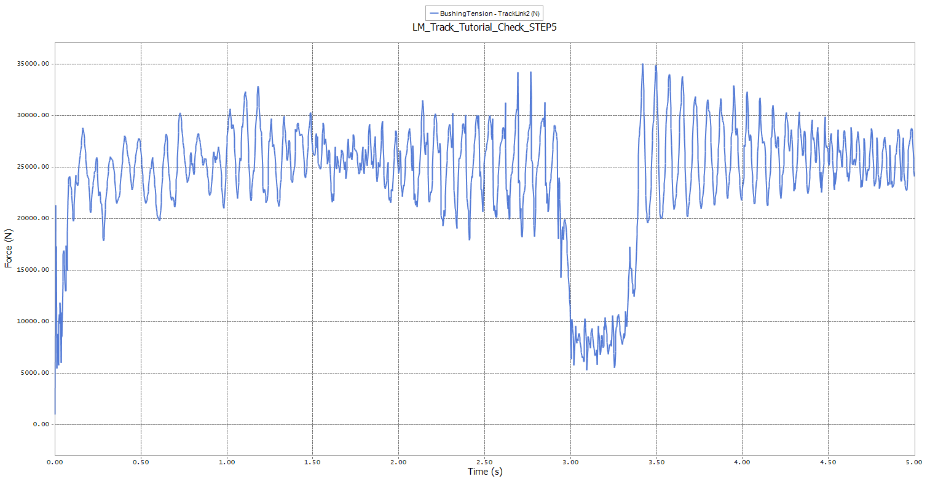
Open the plot window and open the Track-Force group, open the TrackLink2, plot the BushingTension. You will see that the average track tension is approximately 50% of the force in the Tensioner Spring (25,000 N). The low tension occurs when TrackLink2 is in contact with the sprocket.
Adjust the spring properties as needed to attain the desired track tension.
Repeat what you just did (replace fixed joint by translation joint and spring) at Left_Track_Assy for next optional tutorial.
9.10.7. Adding the Blade Linkage (Optional)
In this chapter, you will add a blade assembly (one blade and two side rails to the bulldozer model that you developed earlier. You will add hydraulic cylinders and the constraints needed to raise and lower the blade. You will run the updated bulldozer over the terrain.
9.10.7.1. Task Objective
Learn how to use predefined subsystems and how to add constraints between bodies at the model level and bodies in a subsystem.
9.10.7.2. Estimated Time to Complete
30 minutes
9.10.7.3. Saving a New RecurDyn Model
Because this is an optional exercise, it is a good idea to save the RecurDyn model to a new file so that at a later time you can separately refer to the basic bulldozer model, as well as to the bulldozer model with a blade assembly.
9.10.7.3.1. To save a new RecurDyn model:
From the File menu, choose the Save As function.
Enter the file name LM_Track_Blade.rdyn.
9.10.7.4. Importing and Aligning the Blade Assembly Geometry
The blade assembly consists of the blade and the two side rails. Once imported, the assembly needs to be moved into place with respect to the chassis.
9.10.7.4.1. To import the blade assembly geometry:
From the File menu, choose the Import function. (In the assembly mode).
- In the Open dialog box, set file type to ParaSolid File, and from the Track LM Files folder, select the file Blade_Assy.x_t as shown in the dialog box on the below.(The file path: <InstallDir>\Help\Tutorials\Toolkit\Trak_LM\LowMobilityTrackedVehicle)
Click Open. The CAD Import Options window appears. Clear the Assembly Hierarchy checkbox and click Import.
9.10.7.4.2. To place the blade assembly geometry:
Display the Basic Object Control window.
Make sure that ImportedBody1, ImportedBody2, and ImportedBody3 are selected.
Select the Rotate page, set Degree to 180, and rotate about the global Y axis (in either direction) to flip the blade assembly around.
Click the Translate page, set the Offset Value to 3500, and move the blade assembly in the –X direction.
Set the Offset Value to 200 and move the blade assembly in the –Y direction.
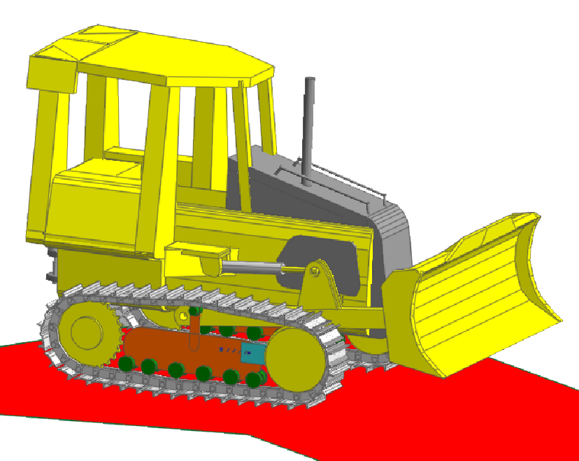
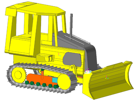
The model should appear as shown in the figure on the below.
To name the blade assembly bodies:
Display the Properties dialog box for each blade assembly body and rename each as follows.
ImportedBody1 to Right_Rail
ImportedBody2 to Left_Rail
ImportedBody3 to Blade
9.10.7.5. Adding Hydraulic Cylinders
A hydraulic cylinder consists of the upper cylinder body and a cylinder rod. It can be tedious to create and align the cylinder bodies with the two connecting points. Instead, you can import a hydraulic cylinder system and then position them using parametric points.
9.10.7.5.1. To import the hydraulic cylinder subsystem:
From the File menu, choose the Import function.
In the Open dialog box, the file type should default to RecurDyn Subsystem File. If not, select that file type.
- From the Track LM Files folder, select the file Hydraulic_Cylinder.rdsb as shown in the dialog box.(The file path: <InstallDir>\Help\Tutorials\Toolkit\Track_LM\LowMobilityTrackedVehicle)
Click Open. The Import SubSystem window appears.
Click OK to create the hydraulic cylinder subsystem.
9.10.7.5.2. To create the second hydraulic cylinder subsystem:
In the Database window, click the SubSystem1 and use the Copy and Paste commands to create a second hydraulic cylinder subsystem, C1_Subsystem1.
Display the Properties dialog box for each subsystem and rename each as follows.
SubSystem1 to Left_Cyl
C1_Subsystem1 to Right_Cyl
9.10.7.6. Positioning the Hydraulic Cylinders
There are parametric points in the hydraulic cylinder subsystems. The hydraulic cylinders will position themselves if you define parametric points at the attachment points of the cylinders in the model level and link (connect) those parametric points to certain parametric points in the subsystems.
9.10.7.6.1. To define the parametric points at the model level:
From the Parameter group in the SubEntity tab, click the Parametric Point function.
Create four parametric points and fill in the text boxes as shown in the figure and as explained below.
Click Add four times.
Name the first point as PP_RCyl and the second point as PP_RRod.
Assign the first point the coordinates of -1460, 440, 650 and the second point the coordinates of -315, 260, 650.
Copy the data from the first point to the third point and the data from the second point to the fourth point. Change the R to L in the names as needed to indicate Left rather than Right. Change the sign of the Z-coordinates to be negative to put the third and fourth points on the other side of the chassis.
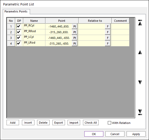
Click OK to create the points and exit the Parametric Points window.
9.10.7.6.2. To link the parametric points and position the hydraulic cylinders:
From the Parameter group in the SubEntity tab, click the Parametric Point Connector function.
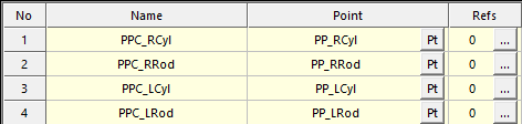
In the Parametric Point Connector List window, click Add four times.
Name the first connector PPC_RCyl and the second point PPC_RRod.
Click Pt for the first connector and drag the name PP_RCyl parametric point by using the mouse or input directly the position information in the Input window Toolbar.
Click ….
The Find Parametric Connector References dialog box appears.
Click >> in the lower right corner.
The Search dialog box appears.
Check the box for PP_Cyl_End for the Right_Cyl subsystem. Then, click Load.
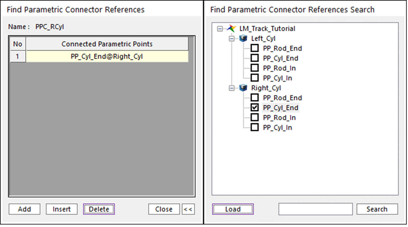
Click Close in the Find Parametric Connector References dialog box.
Create four parametric points and fill in the text boxes as shown in the figure and as explained below.
Parametric PointConnector
Parametric Point Name (model level)
Parametric Point Name (subsystem level)
PPC_RCyl
PP_RCyl
PPC_RRod
PP_RRod
PPC_LCyl
PP_LCyl
PPC_LRod
PP_LRod
Click OK to close the Parametric Point Connector List window and create the connectors.
The two cylinders are now located in the proper locations.
9.10.7.7. Adjusting Size, Colors, and Motion of Hydraulic Cylinders
Now that the hydraulic cylinders are in position, it is easy to see that the size of the cylinder components is too small. You should also adjust the color of the components to match the bulldozer. Finally, you need to add a motion input to the translational joint to contract the hydraulic cylinders by 100 mm so that the blade is in a transport position.
9.10.7.7.1. To adjust the size of the components of each hydraulic cylinder:
Enter the Edit mode for one of the hydraulic cylinders.
Edit the Parametric Values for the hydraulic cylinder subsystem:
Set PV_Cyl_Radius to 60.
Set PV_Rod_Radius to 30.
9.10.7.7.2. To adjust the color of the components of each hydraulic cylinder:
Display the Properties window for Body1 (cylinder rod) and change the color to Gray-25%.
Display the Properties window for Body2 (upper cylinder) and change the color to yellow.
9.10.7.7.3. To adjust the motion of each hydraulic cylinder:
Display the Properties window for joint TraJoint1.
In the Joint page, click Include Motion and click Motion.
Click EL to display the Expression List window.
Click Create to display an Expression window.
Change name to Exp_Cyl_Length
Enter STEP(TIME, 0.1, 0.0, 0.5, -100) in the text box.
Click OK to exit the Expression window.
With Expression 7 selected, click OK to exit the Expression List window.
Click OK to exit the Motion window.
Click OK to exit the TraJoint1 window.
Click the Exit arrow to return to the assembly mode.
Repeat steps 1 through 12 above for the other cylinder.
9.10.7.8. Defining Constraints for the Blade Assembly
In this section, you will create two revolute joint, four spherical joints, a CMotion constraint, and a pair of bushings to properly attach the blade assembly components to each other and to the chassis.
9.10.7.8.1. To define the constraints:
Using the functions of the Joint group in the Professional tab, create the following joints as specified in the table below. Use the Body, Body, Point option to make sure that you are referencing the correct set of bodies, especially when one of them is within one of the two hydraulic cylinder subsystems (see tip below).
Tip
You will notice that when creating a joint, force, or contact; you cannot select a body that is within a subsystem in the normal fashion. However, if you first press down on the Shift key, you will find that are able to select the body with the subsystem.
Create the connection of type |
First Body |
Second Body |
At the location |
|
Joints: |
||||
Revolute |
Chassis |
-1460, 440, 650 |
||
Revolute |
Chassis |
-1460, 440, -650 |
||
Spherical |
Chassis |
Right Rail |
-1775, -90, 650 |
|
Spherical |
Chassis |
Left Rail |
-1775, -90, -650 |
|
Spherical |
Right Rail |
-315, 260, 650 |
||
Spherical |
Left Rail |
-315, 260, -650 |
||
CMotion |
Right Rail |
Blade |
885, -130, 0 (for both points) |
|
Forces: |
||||
Bushing |
Right Rail |
Blade |
659, -280, 650 |
|
Bushing |
Left Rail |
Blade |
659, -280, -650 |
9.10.7.8.2. Adjust the CMotion to fix the blade angle:
Display the Properties dialog box for CMotion1.
Set the Cartesian Motion Type to Displacement (time) and RZ.
Create an expression that has a constant_angle_of_zero (0.0).
9.10.7.8.3. To test the full vehicle model with the blade assembly:
Run a simulation for 5 seconds and 250 steps and compare the animation and plot results to those of the previous animation.
You should observe that the blade rises up to a transport position and then remained fixed as the bulldozer traverses the terrain. You may notice a small vertical motion of the blade relative to the linkage when the bulldozer hits the terrain near the beginning of the simulation. This is due to the compliance of the bushings.
Do you observe any difference in the overall behavior of the bulldozer? You should not see any large changes in behavior, but small changes due to the forward transfer of the center of gravity of the bulldozer due to the weight of the blade assembly. You could plot the vertical loads at the sprocket and the idler for the two cases and see the effect of the weight transfer.