9.8. Media Transport System with IGES Import Tutorial (MTT2D)
9.8.1. Getting Started
9.8.1.1. Objective
The purpose of this tutorial is to acquaint you with the 2D Media Transport Toolkit (MTT2D) and how to simulate the behavior of paper traveling through rollers and guides. You will learn how to import an IGES file and use the imported geometry to define an MTT2D model. It is not unusual for one engineer to design the paper path and for another engineer to do the simulation. The initial paper path design is often considered from the side view as a 2D configuration and it can be represented as 2D lines and arcs in an IGES file. This is the case for this tutorial; the paper path is provided for you in an IGES file and your responsibility is to perform the simulation.
As part of the simulation you will define guides on a body and control roller motion using an event sensor. An event sensor corresponds to a photoelectric cell (or the functional equivalent) that can be used to detect the entrance of the leading edge of the paper into the paper path or the departure of the trailing edge from the paper path.
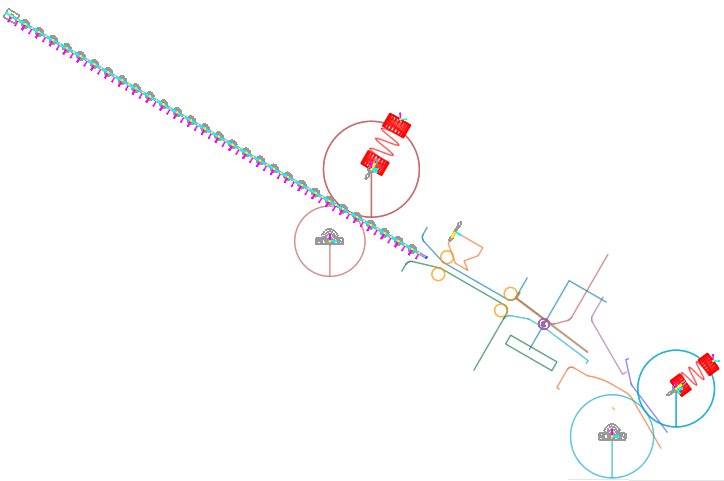
You will create the media transport model shown below. Note that while this example considers the simulation of paper, the media sheet could correspond to a film or any other flexible media.
9.8.1.2. Audience
This tutorial is intended for experienced users of RecurDyn.
9.8.1.3. Prerequisites
Users should first work through the 3D Crank-Slider Tutorial and the Engine with Propeller Tutorial, or the equivalent to under the basics of working with RecurDyn.
9.8.1.4. Procedures
The tutorial is comprised of the following procedures. The estimated time to complete each procedure is shown in the table.
Procedures |
Time (minutes) |
Simulation environment setup |
5 |
Geometry creation |
25 |
Logic creation |
15 |
Analysis and plotting |
10 |
Total |
55 |
9.8.1.5. Estimated Time to Complete
55 minutes
9.8.2. Setting Up Your Simulation Environment
9.8.2.1. Task Objective
Learn how to set up the simulation environment, including units, materials, gravity, and the working plane. Find out how to create a media transport subsystem (2-D).
9.8.2.2. Estimated Time to Complete
5 minutes
9.8.2.3. Starting RecurDyn
9.8.2.3.1. To start RecurDyn and create a new model:
On your Desktop, click the RecurDyn icon. RecurDyn starts and the Star RecurDyn dialog window appears.
Accept the default values.
Click OK.
9.8.2.4. Setting Up the RecurDyn User Environment
In this section, you will create an MTT2D subsystem and turn off the grid and snap-to-grid because you want to snap to the imported IGES geometry and not the grid.
9.8.2.4.1. To set up the environment:
Click the MTT2D function of the Subsystem Toolkit group in the Toolkit tab.
The MTT2D subsystem appears in the database window, and a new toolkit, MTT2D, appears on the ribbon menu.
Turn off Grid and Snap to Grid.
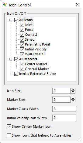
Set the Icon and Marker size to 2.
9.8.2.5. Importing the IGES Geometry
9.8.2.5.1. To import the IGES geometry:
From the File menu, click the Import function.
Set Files of type to IGES and browse to the directory indicated by the instructor.
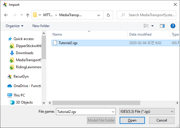
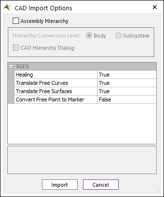
Click Open. The CAD Import Options window appears. Clear the Assembly Hierarchy checkbox and click Import.
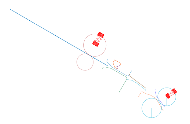
A set of IGES geometry appears in the model window as shown in the graphics to the below. Note that each piece of IGES geometry is an independent body with no mass properties. Before running a simulation, you must make sure that each body is either:
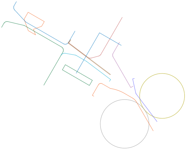
Fixed to ground
Given mass properties
Deleted.
Upcoming steps in the tutorial will address the management of the geometry.
This would be a good time to save your model as MTT2D_IGES.rdyn.
9.8.3. Creating Geometry
You will create new geometry and manage the IGES geometry you imported to create an MTT2D model.
9.8.3.1. Task Objective
Learn to create:
Roller pairs that move the paper
Linear and arc guides that guide the paper
A backstop body to register the paper.
9.8.3.2. Estimated Time to Complete
25 minutes
9.8.3.3. Creating Roller Pairs
You will create two roller pairs: an upper and a lower. You will use existing IGES geometry to create the lower pair and create new geometry for the upper pair.
9.8.3.3.1. To create lower roller pair:
In the MTT2D tab, click the Pair Roller function. Using the Point, Radius, Direction, Radius creation method:
Center Point: Pointing toward to the center of the IGES Geometry labeled 8 in the figure to the below. The crosshair jumps to the center. Click the left mouse button.
Radius: In the command input field, enter 13.
Direction: Pointing toward to the center of the IGES Geometry labeled 7. The crosshair jumps to the center. Click the left mouse button.
Radius: In the command input field, enter 12.
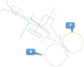
Delete the IGES bodies _CCURVE7 and _CCURVE8 by selecting the body names in the database window and pressing the Delete button on your keyboard.
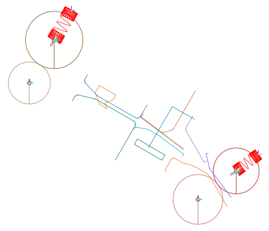
9.8.3.3.2. To create the upper roller pair:
There is no IGES geometry available for use in creating the upper roller pair, so use the data below with the creation method of Point, Radius, Direction, Radius. The graphical result should be similar to the figure on the below.
Center Point: -279.1, 143.5, 0
Radius Point: In the command input field, enter 11.
Direction Point: In the command input field, enter a directional vector of 0.5, 0.866, 0 (30-degree angle).
Radius Point: In the command input field, enter a radius value of 15.
9.8.3.4. Creating Sheet Guides at the Upper Passage
9.8.3.4.1. To create guides entities at the upper section
Using the Guide Convert tool in the MTT2D tab, create Linear Guides and Arc Guides. (see the figure on the below) by selecting the curves. The guides have a contact direction (refer to arrows in the figure) and you want to make sure the guides contact the sheet such that the sheet stays in the passage.
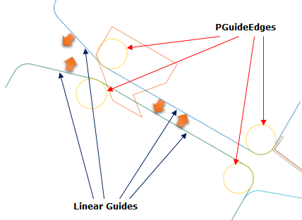
Change the contact direction by using in the MTT2D tab.
Add imaginary PEdge on start and end point of linear guides in Properties dialog box of Linear Guide. The radius is 2.
9.8.3.4.2. To change the color:
Change the color of the guide entities to yellow.
Tip
9.8.3.5. Creating Sheets Guides at the Middle Passage
9.8.3.5.1. To create guides entities at the middle passage:
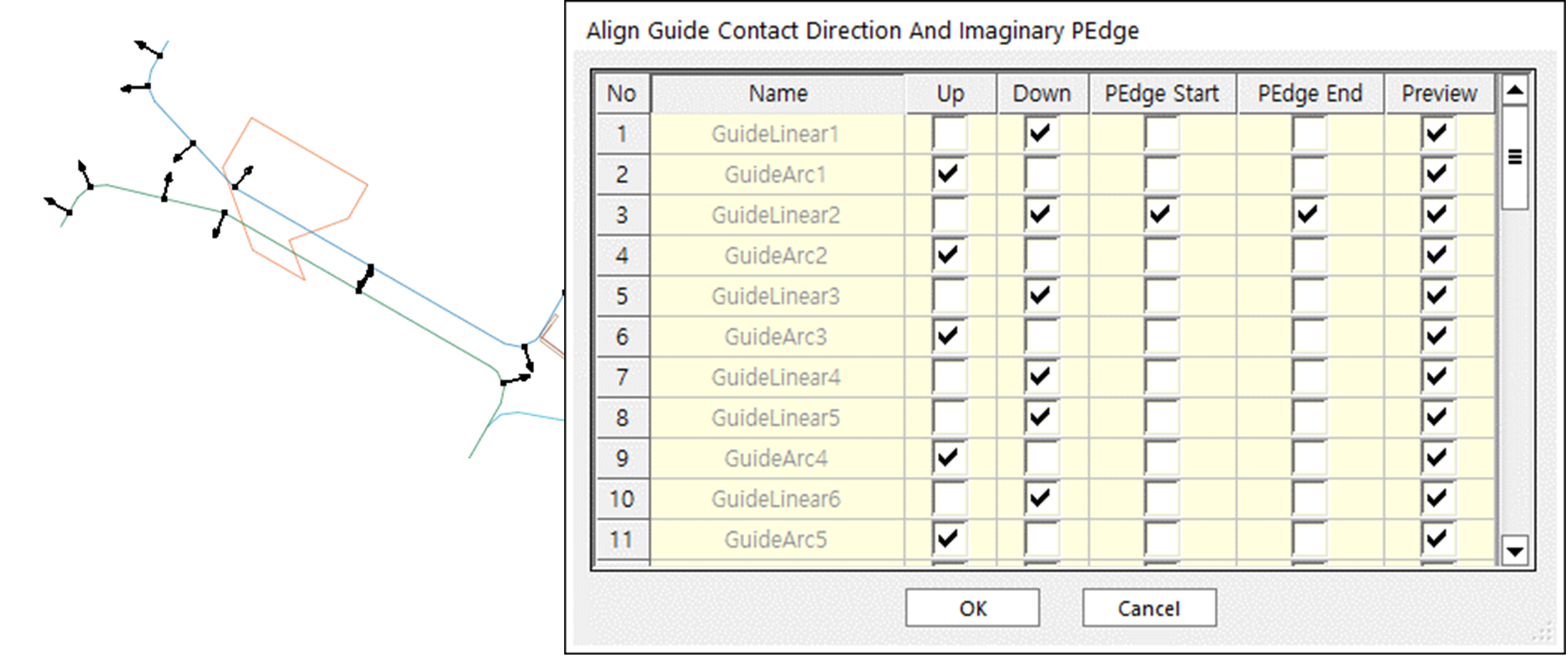
Using the Guide Convert tool in the MTT2D tab, create Linear Guides and Arc Guides. (see the figure on the below) by selecting the curves. The guides have a contact direction (refer to arrows in the figure) and you want to make sure the guides contact the sheet such that the sheet stays in the passage. You can change the contact direction by using Align Guide Contact Direction tool in the MTT2D tab.
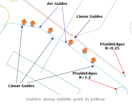
Add imaginary PEdge on start or end point of linear guides in Properties dialog box of Linear Guide. The radiuses and positions refer to the above figure.
As before, change the color of the guide entities to yellow.
9.8.3.6. Creating Sheet Guides at the Lower Section
9.8.3.6.1. To create guides entities at lower section:
Using the Guide Convert tool in the MTT2D tab, create Linear Guides and Arc Guides. (see the figure on the below) by selecting the curves. The guides have a contact direction (refer to arrows in the figure) and you want to make sure the guides contact the sheet such that the sheet stays in the passage. You can change the contact direction by using Align Guide Contact Direction tool in the MTT2D tab.
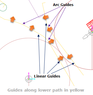
As before, change the color of the guide entities to yellow.
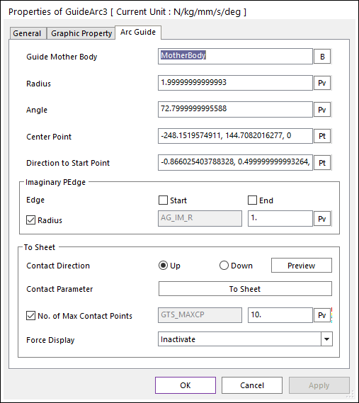
9.8.3.6.2. To check the directionality of the linear and arc guides:
Each guide has a contact direction. Some of the tips above explain how to define the guides such that the contact direction is defined correctly. However, mistakes can happen, and it may be useful to check the contact directionality of each guide.
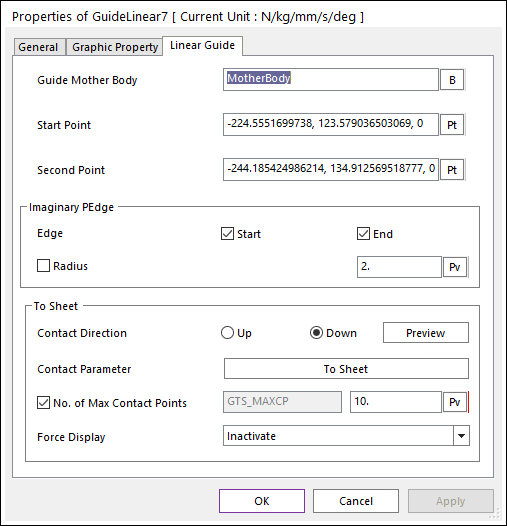
Enter the Properties dialog box and select the Linear Guide or Arc Guide page. There will be a Contact Direction line as shown inside the red rectangle in the figure to the below.
Click Preview to see the contact directionality of the guide entity. The dialog box will disappear, and an arrow will appear that point in the direction that the guide contact will act.
Press the Esc key and the guide dialog box will reappear.
Modify the Contact Direction to Up or Down as needed.
Click OK.
Now would be a good time to save your model.
9.8.3.7. Defining and Moving the Backstop Body
The Backstop body is labeled _CCURVE in the database window.
9.8.3.7.1. To define and move the backstop body:
Delete other ramming curves (_CCURVE4, _CCURVE5, _CURVE11, _CURVE12).
Display the Properties dialog box for the _CCURVE body and rename it to Backstop (use the Name text box in the General page of the Properties dialog box).
Move the Backstop body 2.5 mm in the +X direction and 4.33 mm in the +Y direction.
9.8.3.8. Refining the Backstop Body
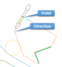
9.8.3.8.1. To refine the backstop body:
Click the Translational Joint function to define a translational joint, using the Point, Direction creation method. Use the two points from the Backstop’s IGES geometry as shown in the figure to the below.
Add linear guides to the Backstop body as shown with the green lines in the figure on the below.
Display the Properties dialog box for each of the linear guides and make the following changes.
Make sure that the Mother Body is the Backstop body.
Click the Contact Parameter to Sheet and from the Contact parameter dialog box that appears, clear the selection of the Stiffness (K).
Change the stiffness value from 1.2 to 12 so that the paper does not pass through the Backstop body.
Tip
In the Contact Parameter window, clear the Stiffness (K) check box.
9.8.4. Adding Logic
In this chapter, you will add a sensor and the controlling logic to the mechanism so that the paper reverses direction once the trailing edge has passed the scan line.
9.8.4.1. Task Objective
Learn how to use an event sensor and control logic to define the motion of a roller pair.
9.8.4.2. Estimated Time to Complete
15 minutes
9.8.4.3. Adding Logic to Reverse the Paper
In this section, you will use an event sensor to define the motion of the fixed rollers and the expression.
9.8.4.3.1. To create an event sensor:
Click the Event Sensor function, and use the Point, Distance creation method. In the Command Input window enter:
-212.1, 117.6, 0 as the location.
1.7 as the distance value.
9.8.4.3.2. Create an expression and assign it to RevJoint1:
Display the Properties dialog box for RevJoint1.
Tip
Make sure to right-click the RevJoint1 entry in the Database Window without having first selected it using a left-click. This will allow you to edit the revolute joint instead of the entire FixedRollerGroup.)
Select Include Motion.
Click Motion.
Change the second pull-down menu from Displacement (time) to Velocity (time).
Click EL (Expression List).
Click Create.
Type in the expression as provided above.
STEP(TIME,0,0,0.1,-40) + SNSR(1)*STEP(TIME,EVTIME(1),0,EVTIME(1)+0.05,80)
The roller velocity smoothly transitions from 0 to -40 radians per seconds. Between 0.00 and 0.05 seconds after the sensor is tripped the roller velocity smoothly transitions from -40 to 40 radians per second.
Change the name to Roller_Velocity.

Click Add to add a text box to the Argument List.
Drag the Event Sensor name (EventSensor1) from the database window into the text box in the Argument List.
Click OK to close the Expression window.
Click OK to close the Expression List window.
The Motion window should appear as shown in the figure to the below.
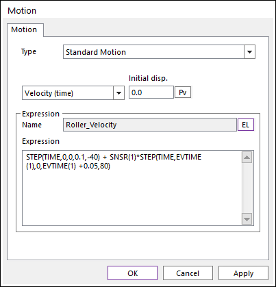
Click OK to close the Motion window.
Click OK to close the Joint window.
Note that when you specify the motion for the other roller you can reuse the same Motion Expression from the Expression List.
9.8.4.3.3. To assign an expression to RevJoint3:
Follow the instructions for RevJoint1 for RevJoint3 but reuse the same Motion Expression from the Expression List instead of creating it again.
This would be a good time to save the model again.
9.8.4.4. Adding Logic to Move the Backstop Body
Use the event sensor to define the motion of the Backstop body in the same way as outlined for creating an expression for TraJoint3. The instructions are summarized below.
9.8.4.4.1. Add logic to move the Backstop body:
Open the properties dialog box of the translational joint and activate the motion.
Click EL and create a new expression.
Name the motion Backstop_Move.
Define the motion expression as shown below.
SNSR(1)*STEP(TIME,EVTIME(1),0,EVTIME(1)+0.05,5)
Click Add to add a text box to the Argument List.
Drag the Event Sensor name (EventSensor1) from the database window into the text box in the Argument List.
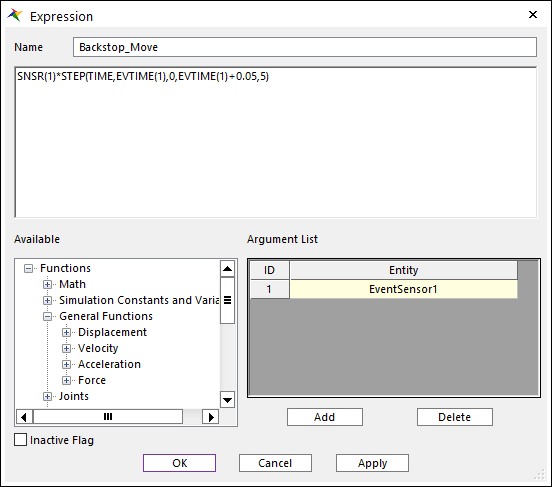
The Backstop body smoothly moves 5 mm into the paper path between 0.00 and 0.05 seconds after the sensor is tripped. Note that this is a displacement (not velocity) motion.
9.8.4.5. Creating the Sheet
9.8.4.5.1. To create the sheet:
In the MTT2D tab, click the Sheet function.
Select the creation method Point, Point, WithDialog.
Click the two points shown below.
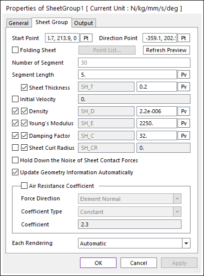
Sheet Start Point: -378.7, 213.9, 0
Sheet End Point: -359.1, 202.5, 0
Modify the Sheet Properties dialog box as needed to match the figure on the below, and then click OK.
9.8.5. Running Simulation and Plotting Results
9.8.5.1. Task Objective
Learn how to run a simulation of the media transport model and plot the contact forces of several of the arc and linear guides.
9.8.5.2. Estimated Time to Complete
10 minutes
9.8.5.3. Running a Dynamic Simulation
9.8.5.3.1. To run a dynamic simulation:
Click the Dynamic / Kinematic Analysis function of the Simulation Type group in the Analysis tab.
Set:
End time to 0.55.
Number of steps to 220.
Plot Multiplier Step Factor to 5.
Select Hide RecurDyn during Simulation.
Click Simulate.
Check the status of the simulation by placing the cursor over the RecurDyn icon in the task bar at the bottom of the screen. As you point at the icon it will report the percent completion of the simulation.
The RecurDyn icon turns green as the simulation progresses and the RecurDyn window reappears when the simulation is complete. The simulation completes in less than a minute on a 2.4GHz or faster computer.
Animate the model using the Play function of the Animation Control group in the Analysis tab. Note how the sheet reverses after the trailing edge passes the scan line. The backstop body moves into place and the roller pair drives the paper into the backstop body. The paper forms an arc as it hits the guides on the Backstop body, resulting in the pressure needed to register the paper. The paper might buckle or wrinkle if the roller pair tried to move the paper much further.
9.8.5.4. Plotting Results
9.8.5.4.1. To plot the output data:
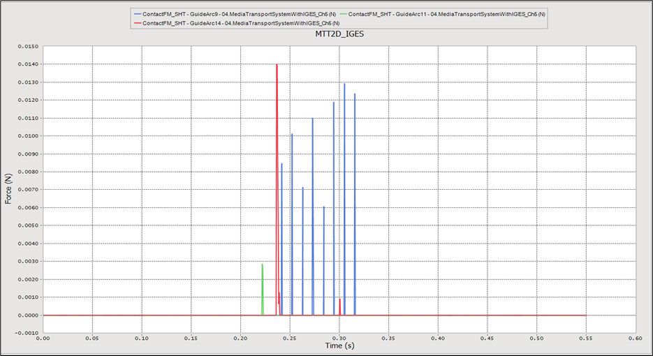
Click the Plot Result function of the Plot group in the Analysis tab.
In the Plot Database Window on the right, expand the Arc Guide item.
Expand the GuideArc9, GuideArc11, and GuideArc14 items.
In each section, double-click ContactFM_SHT.
Adjust the labels and axes so the plot looks like the one next.
9.8.5.5. Optional Analysis
(Optional) Studies of the performance of the MTT2D indicate that the most realistic results occur when the friction type for the sheet to roller contact is set as follows.
Component
Friction Type
Driving Roller
Step
Linear
Linear
Driven (Passive)Roller
Step
Step
Linear
Results
(Default)
Better
Worse
Display the Properties dialog box for each of the two fixed roller groups, click To Sheet and change the friction type to Linear. Rerun the simulation. Are the results improved?
(Optional) Display the Properties dialog box for the Sheet. Click Hold Down the Noise of Sheet Contact Forces and run the simulation again. Are the results improved?