2.2. Dipper Stick with Bucket Tutorial (ProcessNet General)
2.2.1. Overview
2.2.1.1. Task Objectives
ProcessNet is a programming tool based on the .NET framework. It uses classes and variables in the same way as Microsoft Visual Studio does. Therefore, you can use a vast range of programming techniques with ProcessNet. In this tutorial, you will learn how to use ProcessNet to create Windows Forms (WinForms), which are user interfaces based on the .NET framework. You can use WinForms to automate the modelling, analysis, and plotting processes in RecurDyn.
Creating a user interface using WinForms
Automating model creation using a CAD file
Using ProcessNet functions in classes other than ThisApplication
Automating modelling, analysis, and plotting processes using dialog windows
Using Microsoft Visual Studio instead of VSTA
2.2.1.2. Prior Learning Requirements
The model used in this tutorial is based on the Dipper Stick with Bucket, a DOE & Batch simulation tutorial included in the RecurDyn tutorials. Therefore, before starting this tutorial, you must have already completed the Dipper Stick with Bucket tutorial.
2.2.1.3. Prerequisites
You must be well acquainted with Dipper Stick with Bucket tutorial or have performed comparable tasks. Also, you must have basic knowledge on physics.
Task |
Duration (minutes) |
Starting ProcessNet |
5 |
Creating a Dialog Window |
15 |
Automatic Model Generation through Code |
30 |
Analyzing a Model |
10 |
Creating a Plot Automatically |
10 |
Total |
70 |
2.2.1.4. Estimated Time to Complete this Tutorial
This tutorial takes approximately 70 minutes to complete.
2.2.2. Starting ProcessNet General
2.2.2.1. Task Objectives
To learn how to start ProcessNet General in RecurDyn.
2.2.2.2. Estimated Time to Complete this Task
5 minutes
2.2.2.3. Starting RecurDyn
2.2.2.3.1. To start RecurDyn:
Run RecurDyn. The Start RecurDyn dialog window appears.
In the Name field of the New Model group, type Excavator.
Set the Unit to MMKS.
Click OK to create the new model.
2.2.2.3.2. To save the model:
In the File menu, click the Save As function and save the model as Excavator.rdyn in the folder you want.
2.2.2.4. Starting ProcessNet
2.2.2.4.1. To start ProcessNet:
ProcessNet General does not provide the Integrated Development Environment (IDE). So, an IDE program needs to use it. If you don’t have the program, we recommend to use Visual Studio Expression version supported from Microsoft.
To open the ProcessNet integrated development environment (IDE), execute the Visual Studio program. (Visual Studio 2015 Expression version is used in this tutorial.)
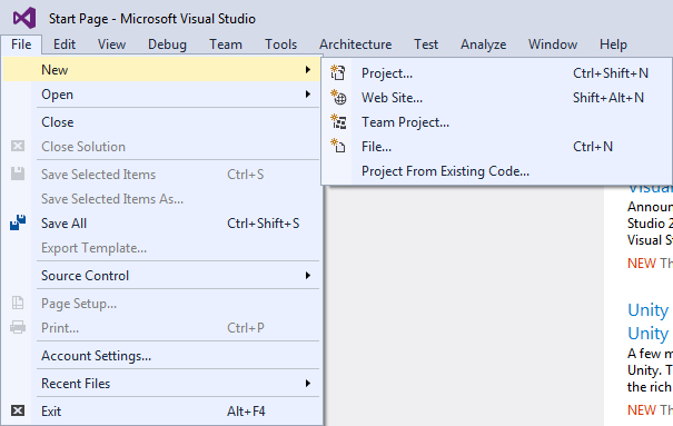
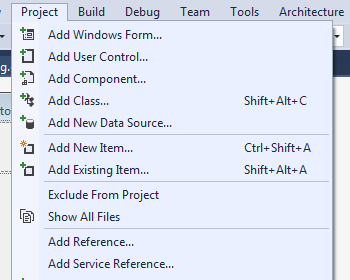
From the File menu, select Project.
When the New Project dialog window appears, select the Template that corresponds to your version of RecurDyn.
Note
You must use the ProcessNet project that is compatible with your version of RecurDyn. If the version is incorrect, then ProcessNet may not execute properly. The New Project dialog window shows all the templates that are compatible with the installed version of RecurDyn.
Select Templates > Visual C# >RecurDyn. And then, click the <RecurDyn Version> ProcessNet CSharp Project icon.
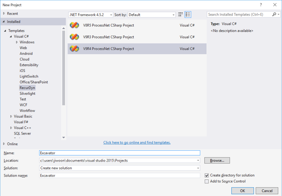
Excavator Project will be created with setting Name, Location, and Solution name as shown in the above figure.
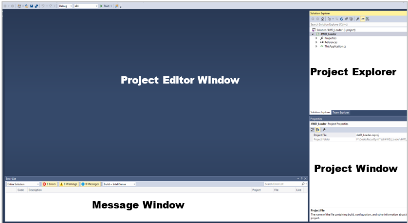
It contains four areas that let you:
Project Editor Window - Write and edit code and design interface objects.
Project Explorer - Get an organized view of your project and its files.
Properties window - View and edit the properties of objects you selected in the Project Editor window or Project Explorer
Message window - View information that is generated as you build and run your code, such as errors in your code.
You are now ready to start developing your first ProcessNet application.
2.2.3. Creating a Dialog Window
In this chapter, you will learn how to create a dialog window and configure its` layout. This includes designing the layout of the dialog window and adding the code to call the dialog window in ProcessNet.
2.2.3.1. Task Objectives
To learn how to create a dialog window and a function to call the dialog window in ProcessNet.
2.2.3.2. Estimated Time to Complete this Task
15 minutes
2.2.3.3. Creating a Dialog Window
2.2.3.3.1. To create a dialog window:
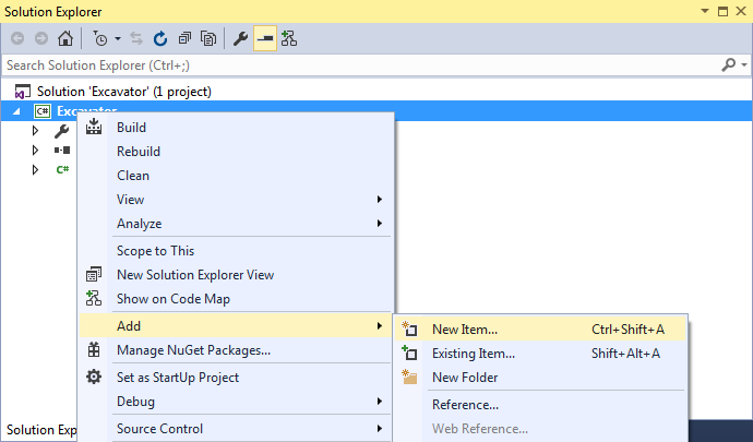
In the Visual Studio, right-click the Project Explorer pane.
Click Add - New Item.
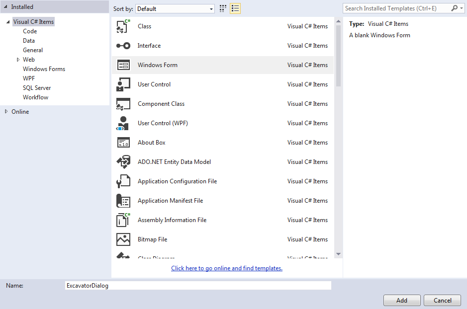
When the Add New Item dialog window appears, click the Windows Form icon, and then type ExcavatorDialog in the name field.
Click Add.
ExcavatorDialog.cs[Design], a design window for Windows Form, appears in the Visual Studio Project Editor pane.
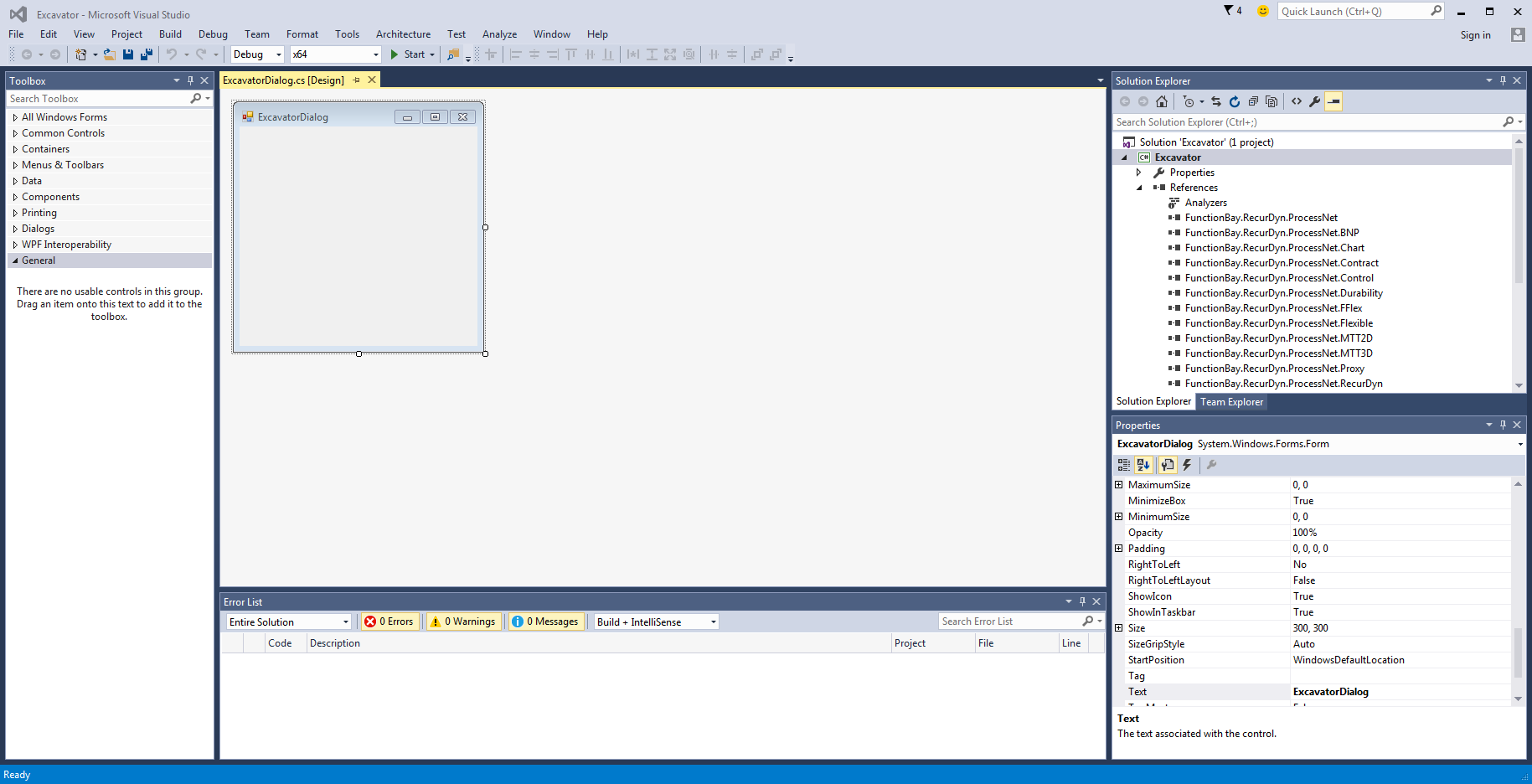
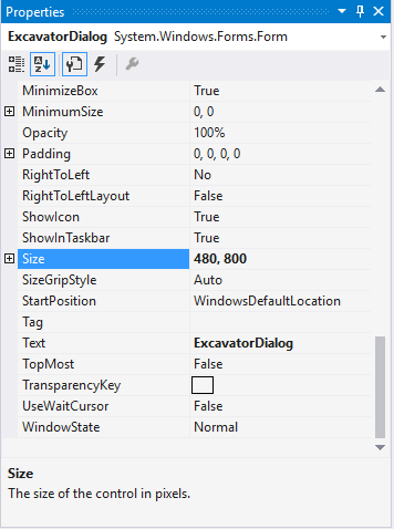
Click the ExcavatorDialog dialog window in the top left corner of the screen.
The information about ExcavatorDialog appears in the Properties pane in the bottom right corner of the screen. In the Properties pane, set the Size to 480, 800.
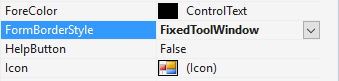
Also, set the FromBorderStyle to FixedToolWindow.
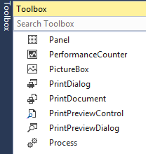
Move the cursor to the Toolbox in the top left corner of the screen. You will see the menu with which you can add a dialog window, button, and other control functions.
Note
If you cannot see the Toolbox, open the View menu, and then click Toolbox or press Ctrl+Alt+X key.
In the Common Controls list, select PictureBox, and then drag and drop the Label in the top left corner of the dialog window that you want to design.
Select the PictureBox you created.
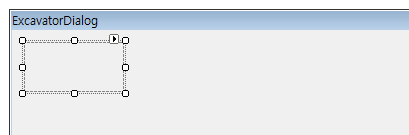
As shown in the figure below, in the Properties pane in the bottom right corner of the screen, click the … button to the right of the Image row.
The Select Resource dialog window appears.
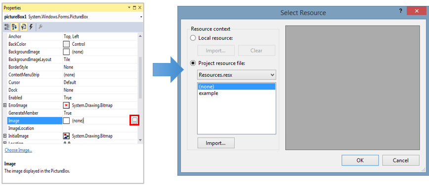
In the Select Resource dialog window, select Local resource, and then click Import.
When the Open dialog window appears, select the picture file to use. (For this tutorial, use the Excavator_1.png file located in the “<InstallDir>\Help\Tutorial\ProcessNet\General\Excavator\Excavator” directory.)
After confirming that the picture is correct, click OK.
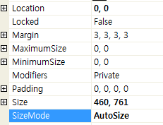
In the Properties pane, set the SizeMode to AutoSize and type 0,0 in the Location field.
Select the Toolbox.
In the Common Controls list, select Label, and then drag and drop the Label in the top left corner of the dialog window that you want to design.
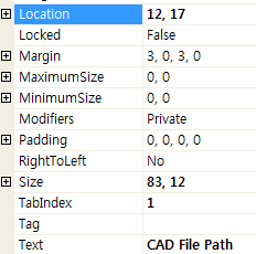
Select the Label you created. Then, in the Properties pane, type CAD File Path in the Text field and type 12,17 in the Location field.
Select the Toolbox again. Then, click and drag the TextBox from the Common Controls list and drop it to the right of the Label.
In the Properties pane for TextBox1 in the top right corner of the window, type 108, 14 in the Location field, tbPath in the Name field, and 260,21 in the Size field.
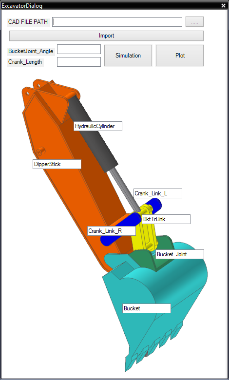
For Button1, Button2, TextBox1, TextBox2, TextBox3, TextBox4, TextBox5, and TextBox6, change the Text and Name values as described in the procedure above by referring to the following table.
DialogElement
Text
Name
Location
Size
Button1
…
btSearchPath
373, 12
75, 23
Button2
Import
btImport
15, 53
433, 23
TextBox1
HydraulicCylinder
tbHydraulicCylinder
161, 251
110, 20
TextBox2
DipperStick
tbDipperStick
68, 364
110, 20
TextBox3
Cra nk_Link_L
tbCrank_Link_L
312, 402
100, 20
TextBox4
Crank_Link_R
tbCrank_Link_R
170, 468
100, 20
TextBox5
BktTrLink
tbBktTrLink
243, 428
100, 20
TextBox6
Bucket_Joint
tbBucket_Joint
282, 508
100, 20
TextBox7
Bucket
tbBucket
258, 614
100, 20
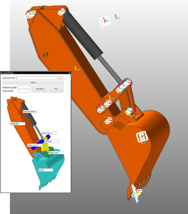
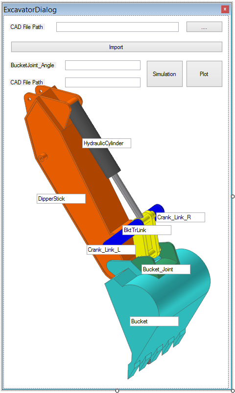
After setting all of the values described above, the dialog window should resemble the figure below.
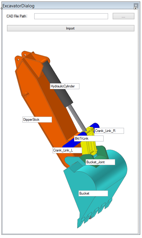
Open the File menu and click Save ExcavatorDialog.cs to save the file.
Note
The size or location of the dialog window may differ depending on the PC environment.
2.2.3.4. Configuring the Initial Settings of the Dialog Window
The previous procedure configured the appearance of the dialog window. Now, you must add variables to the dialog window to define what values users can enter and the event generated when users click a button. Also, you will also learn how to use the ProcessNet function in the dialog window.
2.2.3.4.1. To configure the initial settings of the dialog window:
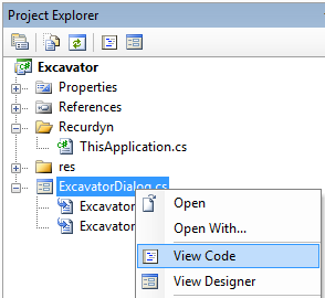
In the Project Explorer, right-click ExcavatorDialog.cs. In the context menu, click View Code to display the source code for ExcavatorDialog.cs in the Project Editor window.
In the Project Editor window, enter the variables to be used in the dialog window.
FunctionBay.RecurDyn.ProcessNet provides the reference information to use in ProcessNet functions.
IApplication is the interface used to recognize RecurDyn.
The strFilePath and StrExcavatorPartName are the string to display and the path of the CAD file or subsystem file to use when Excavator does not exist, respectively.
using System.Windows.Forms;
using FunctionBay.RecurDyn.ProcessNet;

namespace Excavator
{
    public partial class ExcavatorDialog : Form
    {
        IApplication application;
        string strFilePath;
        string[,] strExcavatorPartName = new string[7, 2];
        public ExcavatorDialog(IApplication app)
        {
            InitializeComponent();
            application = app;
                   }
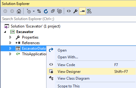
In the Project Explorer, right-click ExcavatorDialog.cs, and then click View Designer to display the dialog window you created in the previous procedure.
In the dialog window, double-click the … button to create the function to call when the user double-clicks a button.
Insert the following code to create the function automatically.
This code imports the folder path from the Folder Dialog window.
Click the … button to execute the btSearchPatch_Click() function and create the Folder Dialog window.
private void btSearchPath_Click(object sender, EventArgs e)
{
    FolderBrowserDialog dialog = new FolderBrowserDialog();
    dialog.ShowDialog();
    this.tbPath.Text = dialog.SelectedPath;
}
In the Project Explorer, right-click ExcavatorDialog.cs, and then click View Designer. In the dialog window, double-click the Import button to create the btImport_Click() function.
Under the btImport_Click () function, create a new function called UpdateDB() and enter the following code.
The UpdateDB() function stores the variable entered in the textbox of the dialog window.
The This.tbPath.text procedure retrieves the value entered in the textbox named tbPath.
The strExcavatorPartName is a two-dimensional array that saves the name and path of a CAD file or subsystem file.
private void UpdateDB()
{
    strFilePath = this.tbPath.Text;
    strExcavatorPartName[0, 0] = this.tbDipperStick.Text.ToString();
    strExcavatorPartName[0, 1] = strFilePath + @"\" + this.tbDipperStick.Text.ToString() + ".x_t";
    strExcavatorPartName[1, 0] = this.tbCrank_Link_L.Text.ToString();
    strExcavatorPartName[1, 1] = strFilePath + @"\" + this.tbCrank_Link_L.Text.ToString() + ".x_t";
    strExcavatorPartName[2, 0] = this.tbCrank_Link_R.Text.ToString();
    strExcavatorPartName[2, 1] = strFilePath + @"\" + this.tbCrank_Link_R.Text.ToString() + ".x_t";
    strExcavatorPartName[3, 0] = this.tbBucket.Text.ToString();
    strExcavatorPartName[3, 1] = strFilePath + @"\" + this.tbBucket.Text.ToString() + ".x_t";
    strExcavatorPartName[4, 0] = this.tbBucket_Joint.Text.ToString();
    strExcavatorPartName[4, 1] = strFilePath + @"\" + this.tbBucket_Joint.Text.ToString() + ".x_t";
    strExcavatorPartName[5, 0] = this.tbBktTrLink.Text.ToString();
    strExcavatorPartName[5, 1] = strFilePath + @"\" + this.tbBktTrLink.Text.ToString() + ".rdsb";
    strExcavatorPartName[6, 0] = this.tbHydraulicCylinder.Text.ToString();
    strExcavatorPartName[6, 1] = strFilePath + @"\" + this.tbHydraulicCylinder.Text.ToString() + ".rdsb";
}
Insert the following code to create the function automatically.
The code executes the UpdateDB() function when a user clicks the Import button in the dialog window.
private void btImport_Click(object sender, EventArgs e)
{
    UpdateDB();
}
In the File menu, click Save ExcavatorDialog.cs to save the file.
2.2.3.5. Displaying a Dialog Window when the User Runs the Application
This section teaches you how to display a dialog window when a user runs the ProcessNet application in RecurDyn and how to make a dialog window dependent on RecurDyn.
2.2.3.5.1. To display a dialog window when a user runs the application:
In the Project Explorer, double-click ThisApplication.cs.
In the ThisApplication.cs file, delete the HelloProcessNet() and CreateBodyExample() functions marked with strikethroughs, as shown below. (These functions are generated automatically as an example.)
̶p̶u̶b̶l̶i̶c̶ ̶v̶o̶i̶d̶ ̶H̶e̶l̶l̶o̶P̶r̶o̶c̶e̶s̶s̶N̶e̶t̶(̶)̶
̶{̶
    ̶/̶/̶a̶p̶p̶l̶i̶c̶a̶t̶i̶o̶n̶ ̶i̶s̶ ̶a̶s̶s̶i̶g̶n̶e̶d̶ ̶a̶t̶ ̶I̶n̶i̶t̶i̶a̶l̶i̶z̶e̶(̶)̶ ̶s̶u̶c̶h̶ ̶a̶s̶
    ̶/̶/̶a̶p̶p̶l̶i̶c̶a̶t̶i̶o̶n̶ ̶=̶ ̶R̶e̶c̶u̶r̶D̶y̶n̶A̶p̶p̶l̶i̶c̶a̶t̶i̶o̶n̶ ̶a̶s̶ ̶I̶A̶p̶p̶l̶i̶c̶a̶t̶i̶o̶n̶;̶
    ̶a̶p̶p̶l̶i̶c̶a̶t̶i̶o̶n̶.̶P̶r̶i̶n̶t̶M̶e̶s̶s̶a̶g̶e̶(̶"̶H̶e̶l̶l̶o̶ ̶P̶r̶o̶c̶e̶s̶s̶N̶e̶t̶"̶)̶;̶
    ̶a̶p̶p̶l̶i̶c̶a̶t̶i̶o̶n̶.̶P̶r̶i̶n̶t̶M̶e̶s̶s̶a̶g̶e̶(̶a̶p̶p̶l̶i̶c̶a̶t̶i̶o̶n̶.̶P̶r̶o̶c̶e̶s̶s̶N̶e̶t̶V̶e̶r̶s̶i̶o̶n̶)̶;̶
̶}̶

̶p̶u̶b̶l̶i̶c̶ ̶v̶o̶i̶d̶ ̶C̶r̶e̶a̶t̶e̶B̶o̶d̶y̶E̶x̶a̶m̶p̶l̶e̶(̶)̶
̶{̶
    ̶r̶e̶f̶F̶r̶a̶m̶e̶1̶ ̶=̶ ̶m̶o̶d̶e̶l̶D̶o̶c̶u̶m̶e̶n̶t̶.̶C̶r̶e̶a̶t̶e̶R̶e̶f̶e̶r̶e̶n̶c̶e̶F̶r̶a̶m̶e̶(̶)̶;̶
    ̶r̶e̶f̶F̶r̶a̶m̶e̶1̶.̶S̶e̶t̶O̶r̶i̶g̶i̶n̶(̶1̶0̶0̶,̶ ̶0̶,̶ ̶0̶)̶;̶

    ̶r̶e̶f̶F̶r̶a̶m̶e̶2̶ ̶=̶ ̶m̶o̶d̶e̶l̶D̶o̶c̶u̶m̶e̶n̶t̶.̶C̶r̶e̶a̶t̶e̶R̶e̶f̶e̶r̶e̶n̶c̶e̶F̶r̶a̶m̶e̶(̶)̶;̶
    ̶r̶e̶f̶F̶r̶a̶m̶e̶2̶.̶S̶e̶t̶O̶r̶i̶g̶i̶n̶(̶0̶,̶ ̶2̶0̶0̶,̶ ̶0̶)̶;̶

    ̶I̶B̶o̶d̶y̶ ̶b̶o̶d̶y̶1̶ ̶=̶ ̶m̶o̶d̶e̶l̶.̶C̶r̶e̶a̶t̶e̶B̶o̶d̶y̶B̶o̶x̶(̶"̶b̶o̶d̶y̶1̶"̶,̶ ̶r̶e̶f̶F̶r̶a̶m̶e̶1̶,̶ ̶1̶5̶0̶,̶ ̶1̶0̶0̶,̶ ̶1̶0̶0̶)̶;̶
    ̶a̶p̶p̶l̶i̶c̶a̶t̶i̶o̶n̶.̶P̶r̶i̶n̶t̶M̶e̶s̶s̶a̶g̶e̶(̶b̶o̶d̶y̶1̶.̶N̶a̶m̶e̶)̶;̶
    ̶I̶B̶o̶d̶y̶ ̶b̶o̶d̶y̶2̶ ̶=̶ ̶m̶o̶d̶e̶l̶.̶C̶r̶e̶a̶t̶e̶B̶o̶d̶y̶S̶p̶h̶e̶r̶e̶(̶"̶b̶o̶d̶y̶2̶"̶,̶ ̶r̶e̶f̶F̶r̶a̶m̶e̶2̶,̶ ̶5̶0̶)̶;̶
    ̶a̶p̶p̶l̶i̶c̶a̶t̶i̶o̶n̶.̶P̶r̶i̶n̶t̶M̶e̶s̶s̶a̶g̶e̶(̶b̶o̶d̶y̶2̶.̶N̶a̶m̶e̶)̶;̶
̶}̶
Write the Run() function shown below.
This function creates a new instance of ExcavatorDialog.
It delivers the values of Application and MainWindow to the ExcavatorDialog class.
Note
The Application and MainWindow values must be delivered to this class to use ProcessNet methods in WinForms.
public void Run()
{
    ExcavatorDialog DialogRun = new ExcavatorDialog(application);
    DialogRun.ShowDialog();
}
In the File menu, click Save ThisApplication.cs to save the file.
2.2.3.6. Testing a Dialog Window
In this section, you will test whether the application created above works properly.
2.2.3.6.1. To run the application:
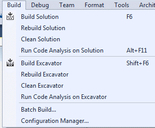
Check if any errors or warnings appear in the Error List pane at the bottom of the IDE window. If there are any errors or warnings, correct the problems. In the Build menu, click Build Solution.
In RecurDyn, on the Customize tab, in the ProcessNet(General) group, click the Run function.
In the tree in the lower half of the ProcessNet Manager dialog window, click Run under Excavator.
In the ProcessNet Manager dialog window, click Run.
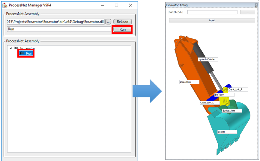
The created dialog window appears.
Once you confirm that the application runs properly, close the dialog window.
Close the ProcessNet Manager dialog window.
2.2.4. Automatic Model Generation through Code
2.2.4.1. Task Objectives
In this chapter, you will create a new class and write a ProcessNet function under that class. Then, you will learn how to call this function in the dialog window created in the previous chapter.
2.2.4.2. Estimated Time to Complete this Task
30 minutes
2.2.4.3. Creating a New Class
This section teaches you how to create a new class and enter a ProcessNet function under that class.
2.2.4.3.1. To create a new class:
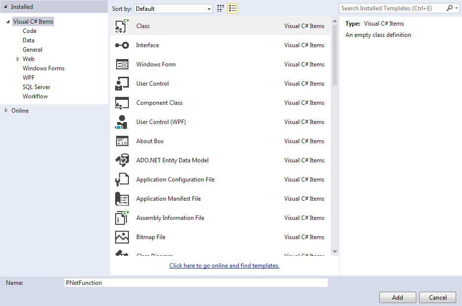
In the Visual Studio, click Project - Add New Item.
When the Add New Item dialog window appears, select Class in the Templates pane and type PNetFunction in the Name field. Then, click Add.
When the PNetFunction.cs appears in the Project Editor pane, enter the following code. This code resets the basic variables used to execute a ProcessNet function.
IApplication: Used to recognize RecurDyn
IModelDocument: A model document used in RecurDyn
ISubsystem: A subsystem used in the model document
IReferenceFrame: A reference frame of RecurDyn
IPlotDocument: A RecurDyn plot document
using FunctionBay.RecurDyn.ProcessNet;
namespace Excavator
{
    class PNetFunction
    {
        static public IApplication application;
        public IModelDocument modelDocument = null;
        public IPlotDocument plotDocument = null;
        public ISubSystem model = null;

        public IReferenceFrame refFrame1 = null;
        public IReferenceFrame refFrame2 = null;

        public PNetFunction(IApplication app)
        {
        application = app;
        }
    }
}
In the File menu, click Save PNetFunction.cs to save the file.
2.2.4.4. Creating a Model
In this section, you will learn how to create an Excavator model automatically.
2.2.4.4.1. To import a body:
Write a code that creates an Excavator model using a CAD file and Subsystem file.
Create the following Import() function.
public void Import(string[,] strExcavatorPartName)
{
}
Then, insert the following variable declaration in the Import() function.
modelDocument = application.ActiveModelDocument;
model = modelDocument.Model;

refFrame1 = modelDocument.CreateReferenceFrame();
refFrame1.SetOrigin(0, 0, 0);
refFrame2 = modelDocument.CreateReferenceFrame();
refFrame2.SetOrigin(0, 0, 0);
After the variable declaration, add the following loop to import the *.x_t and *.rdsb files. The *.x_t files are the CAD files for the respective parts of the model and the *.rdsb files are the subsystem files.
FileImport() imports the CAD and subsystem files.
Crank Link R creates a marker without importing the CAD files. So, a continue statement is used to go to the next loop.
for(int iCount = 0; iCount < 7; iCount++)
{
      if( iCount == 2)
      continue;
      model.FileImport(strExcavatorPartName[iCount,1]);
}
Enter the following code to use the SubSystemCollection property to compose a list of subsystems in the model and then declares the subsystems as Sub01, Sub02, and so on.
ISubSystemCollection SubCollection01 = model.SubSystemCollection;
ISubSystem Sub01 = SubCollection01[0];
ISubSystem Sub02 = SubCollection01[1];
Use the GetEntity() function to search the imported body.
The GetEntity() function searches the entities in RecurDyn.
Basically, IGeneric is returned for the function. The function can perform type conversion according to the type of entity you want.
IBody BodyDipperStick = model.GetEntity(strExcavatorPartName[0,0]) as IBody;
IBody BodyCrankLinkL = model.GetEntity(strExcavatorPartName[1, 0]) as IBody;
IBody BodyBucket = model.GetEntity(strExcavatorPartName[3, 0]) as IBody;
IBody BodyJoint = model.GetEntity(strExcavatorPartName[4, 0]) as IBody;

IBody BodyBktTrLink_CylRod_Cylinder = Sub01.GetEntity("BktTrLink_CylRod_Cylinder") as IBody;
IBody BodyBktTrLink_Bucket_BktTrLink_Cylinder = Sub01.GetEntity("Bucket_BktTrLink_Cylinder") as IBody;
IBody BodyBktTrLink_Right_Link = Sub01.GetEntity("Right_Link") as IBody;
IBody BodyHydraulicCylinder_Cylinder =    Sub02.GetEntity("Cylinder") as IBody;
IBody BodyHydraulicCylinder_Rod = Sub02.GetEntity("Rod") as IBody;
IBody BodySub02Mother = Sub02.GetEntity("MotherBody") as IBody;

IParametricPoint SubPP_BktTrLink_CylRod = Sub01.GetEntity("PP_BktTrLink_CylRod") as IParametricPoint;
IParametricPoint SubPP_BktTrLink_Rod = Sub01.GetEntity("PP_BktTrLink_Rod") as IParametricPoint;
IParametricPoint SubPP_Bucket_BktTrLink = Sub01.GetEntity("PP_Bucket_BktTrLink") as IParametricPoint;
IParametricPoint SubPP_CrankL_BktTrLink = Sub01.GetEntity("PP_CrankL_BktTrLink") as IParametricPoint;
IParametricPoint SubPP_CrankR_BktTrLink = Sub01.GetEntity("PP_CrankR_BktTrLink") as IParametricPoint;

IParametricPoint SubPP_Cyl_End = Sub02.GetEntity("PP_Cyl_End") as IParametricPoint;
IParametricPoint SubPP_Rod_End = Sub02.GetEntity("PP_Rod_End") as IParametricPoint;
Enter the following code to generate a marker in the link body called Crank_Link_R and the Bucket_Joint body.
Crank_Link_R creates a marker instead of importing the CAD file so that you can control the model posture by entering the PP in its second variable.
IBody BodyCrankLinkR = model.CreateBodyLinkWithRadius(strExcavatorPartName[2, 0], new double[] { 5506.1017, -495.8525, 2231.9958 }, new double[] { 5606.1017, -495.8525, 2231.9958 },100,100, 35);
BodyCrankLinkR.Graphic.Color = 26367;

refFrame1.SetOrigin(6060.3717, -207.8525, 1993.4767);
refFrame1.SetEulerAngleDegree(EulerAngle.EulerAngle_ZXZ, 180, 90, 90);
IMarker Marker01 = BodyJoint.CreateMarker("Marker1", refFrame1);
Declare the ground of the assembly mode as bodyground.
IBody BodyGround = model.Ground;
Create a dummy body.
refFrame1.SetOrigin(5579.2685, -207.8525, 62.560441);
IBody BodyDummyBucketTip = model.CreateBodyEllipsoid("BucketTip", refFrame1, 50, 50, 50);
refFrame1.SetOrigin(6100, -207.8525, 4200);
IBody BodyDummyDrivingForceBody = Sub02.CreateBodyEllipsoid("DrivingForceBody", refFrame1, 50, 50, 50);
In the File menu, click Save PNetFunction.cs to save the file.
2.2.4.4.2. To create a SubEntity:
In this section, you will create the SubEntity to be used in the Excavator model.
Add the following code to create the PVs in the Import() function created in the previous procedure.
(All the codes from creating the SubEntity to creating the variable equations should be added consecutively with the same indentation inside the Import() function.)
IParametricValue PV_DeltaCrankLength = model.CreateParametricValue("PV_DeltaCrankLength", 0);
IParametricValue PV_BucketJointAngleDeg = model.CreateParametricValue("PV_BucketJointAngleDeg", 0);
IParametricValue PV_BucketJointAngle = model.CreateParametricValue("PV_BucketJointAngle", 0);
IParametricValue PV_BktTrLink_CylRod_X = model.CreateParametricValue("PV_BktTrLink_CylRod_X", 0);
IParametricValue PV_BktTrLink_CylRod_Z = model.CreateParametricValue("PV_BktTrLink_CylRod_Z", 0);
IParametricValue PV_BucketJointOriginX = model.CreateParametricValue("PV_BucketJointOriginX", 0);
IParametricValue PV_BucketJointOriginZ = model.CreateParametricValue("PV_BucketJointOriginZ", 0);
IParametricValue PV_Cyl_Amplitude = model.CreateParametricValue("PV_Cyl_Amplitude", 350);
Add a code that creates the following expressions under the code that creates the PVs.
IExpression Ex_Deg2Rad = model.CreateExpression("Ex_Deg2Rad", "PV_BucketJointAngleDeg*PI/180");
IExpression Ex_BktTrLink_CylRod_X = model.CreateExpression("Ex_BktTrLink_CylRod_X", "COS(0.291724-ACOS(((704.58305+PV_DeltaCrankLength)*(704.58305+PV_DeltaCrankLength)-10996911)/(-10963694)))*965.471+SIN(0.291724-ACOS(((704.58305+PV_DeltaCrankLength)*(704.58305+PV_DeltaCrankLength)-10996911)/(-10963694)))*(-2034.522)+5139.0782");
IExpression Ex_BktTrLink_CylRod_Z = model.CreateExpression("Ex_BktTrLink_CylRod_Z", "-SIN(0.291724-ACOS(((704.58305+PV_DeltaCrankLength)*(704.58305+PV_DeltaCrankLength)-10996911)/(-10963694)))*965.471+COS(0.291724-ACOS(((704.58305+PV_DeltaCrankLength)*(704.58305+PV_DeltaCrankLength)-10996911)/(-10963694)))*(-2034.522)+4638.4021");
IExpression Ex_BucketJointOriginX = model.CreateExpression("Ex_BucketJointOriginX", "(1-COS(PV_BucketJointAngle))*6191.0835-SIN(PV_BucketJointAngle)*1340.8818");
IExpression Ex_BucketJointOriginZ = model.CreateExpression("Ex_BucketJointOriginZ", "SIN(PV_BucketJointAngle)*6191.0835+(1-COS(PV_BucketJointAngle))*1340.8818");
IExpression Ex_BucketTipLoad = model.CreateExpression("Ex_BucketTipLoad", "0");
IExpression Ex_DrivingForce = Sub02.CreateExpression("Ex_DrivingForce", "0");
Ex_DrivingForce.Arguments = new string[] { "Cylinder.Marker1@HydraulicCylinder", "Rod.Marker1@HydraulicCylinder" };
Ex_DrivingForce.Text = "FZ(1,2,2)";
Add a code that generates values for the PVs under the code that creates each expression.
After creating an expression, enter the values for the PVs. When the following code is executed, the values of the PVs change to the expressions shown below.
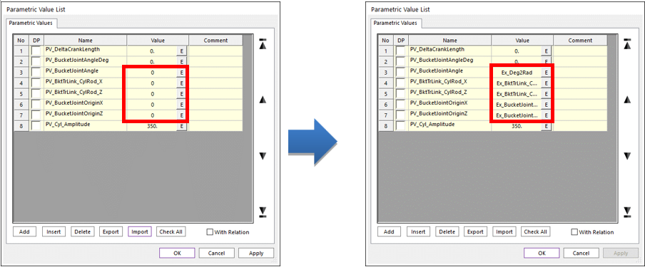
PV_BucketJointAngle.Text = "Ex_Deg2Rad";
PV_BktTrLink_CylRod_X.Text = "Ex_BktTrLink_CylRod_X";
PV_BktTrLink_CylRod_Z.Text = "Ex_BktTrLink_CylRod_Z";
PV_BucketJointOriginX.Text = "Ex_BucketJointOriginX";
PV_BucketJointOriginZ.Text = "Ex_BucketJointOriginZ";
Once the values for PVs are set, add the following code to create PPs.
IParametricPoint PP_CrankL_BktTrLink = model.CreateParametricPointWithText("PP_CrankL_BktTrLink", "PV_BktTrLink_CylRod_X,80.147498,PV_BktTrLink_CylRod_Z", null);
IParametricPoint PP_Bucket_BktTrLink = model.CreateParametricPoint("PP_Bucket_BktTrLink", new double[] { 0, 0, 0 }, null);
IParametricPoint PP_BktTrLink_Rod = model.CreateParametricPointWithText("PP_BktTrLink_Rod", "PV_BktTrLink_CylRod_X,-207.85255,PV_BktTrLink_CylRod_Z", null);
IParametricPoint PP_DipperStick_Cyl = model.CreateParametricPoint("PP_DipperStick_Cyl", new double[] { 5139.0782, -207.85255, 4638.4021 }, null);
IParametricPoint PP_BucketJointOrigin = model.CreateParametricPointWithText("PP_BucketJointOrigin", " PV_BucketJointOriginX,0.,PV_BucketJointOriginZ", null);
IParametricPoint PP_CrankR_BktTrLink = model.CreateParametricPointWithText("PP_CrankR_BktTrLink", "PV_BktTrLink_CylRod_X,-495.8525, PV_BktTrLink_CylRod_Z", null);
PP_Bucket_BktTrLink.RefMarker = Marker01;
Under the code that creates the PPs, add the following code to create the PPCs and PVCs.
IParametricPointConnector PPC_Bucket_BktTrLink = model.CreateParametricPointConnector("PPC_Bucket_BktTrLink");
PPC_Bucket_BktTrLink.Point.ParametricPoint = PP_Bucket_BktTrLink;
PPC_Bucket_BktTrLink.Add(SubPP_Bucket_BktTrLink);
IParametricPointConnector PPC_BktTrLink_CylRod = model.CreateParametricPointConnector("PPC_BktTrLink_CylRod");
PPC_BktTrLink_CylRod.Point.ParametricPoint = PP_BktTrLink_Rod;
PPC_BktTrLink_CylRod.Add(SubPP_BktTrLink_CylRod);

IParametricPointConnector PPC_CrankL_BktTrLink = model.CreateParametricPointConnector("PPC_CrankL_BktTrLink");
PPC_CrankL_BktTrLink.Point.ParametricPoint = PP_CrankL_BktTrLink;
PPC_CrankL_BktTrLink.Add(SubPP_CrankL_BktTrLink);
IParametricPointConnector PPC_BktTrLink_Rod = model.CreateParametricPointConnector("PPC_BktTrLink_Rod");
PPC_BktTrLink_Rod.Point.ParametricPoint = PP_BktTrLink_Rod;
PPC_BktTrLink_Rod.Add(SubPP_BktTrLink_Rod);
PPC_BktTrLink_Rod.Add(SubPP_Rod_End);
IParametricPointConnector PPC_CrankR_BktTrLink = model.CreateParametricPointConnector("PPC_CrankR_BktTrLink");
PPC_CrankR_BktTrLink.Point.ParametricPoint = PP_CrankR_BktTrLink;
PPC_CrankR_BktTrLink.Add(SubPP_CrankR_BktTrLink);
IParametricPointConnector PPC_Cyl_End = model.CreateParametricPointConnector("PPC_Cyl_End");
PPC_Cyl_End.Point.ParametricPoint = PP_DipperStick_Cyl;
PPC_Cyl_End.Add(SubPP_Cyl_End);
Under the code that creates the PPCs and PVCs, add the following code to change the second point and normal direction of Crank_Link_R.
IGeometryLink GeoLink1 = BodyCrankLinkR.GetEntity("Link1") as IGeometryLink;
GeoLink1.SecondParametricPoint = PP_CrankR_BktTrLink;
GeoLink1.SetNormalDirection(0, 1, 0);
In the File menu, click Save PNetFunction.cs to save the file.
2.2.4.4.3. To create a joint:
In this section, you will create the joints to be used in the Excavator model.
In the Import() function created in the previous procedure, add the following code to create the fixed joints.
refFrame1.SetOrigin(4440.16, -387.85255, 4768.1811);
refFrame1.SetEulerAngleDegree(EulerAngle.EulerAngle_ZXZ, 0, 90, 0);
IJointFixed FixedJoint_Dipper_Ground = model.CreateJointFixed("Fixed_Dipper_Ground", BodyGround, BodyDipperStick, refFrame1);

refFrame1.SetOrigin(6191.0835, -207.8525, 1340.8818);
refFrame1.SetEulerAngleDegree(EulerAngle.EulerAngle_ZYX, 0, 0, 0);
IJointFixed FixedJoint_Bucket_BucketJoint = model.CreateJointFixed("Fixed_Bucket_BucketJoint", BodyBucket, BodyJoint, refFrame1);
FixedJoint_Bucket_BucketJoint.BaseMarker.RefFrame.EulerAngle.Beta.ParametricValue = PV_BucketJointAngle;

refFrame1.SetOrigin(5679.2685, -207.8525, 62.560441);
refFrame1.SetEulerAngleDegree(EulerAngle.EulerAngle_ZXZ, 0, 90, 0);
IJointFixed FixedJoint_BucketTip_Bucket = model.CreateJointFixed("Fixed_BucketTip_Bucket", BodyDummyBucketTip, BodyBucket, refFrame1);

refFrame1.SetOrigin(6100, -207.8525, 4200);
refFrame1.SetEulerAngleDegree(EulerAngle.EulerAngle_ZXZ, 0, 0, 0);
IJointFixed FixedJoint_DrivingForceBody = model.CreateJointFixed("Fixed_DrivingForceBody", BodyGround, BodyDummyDrivingForceBody, refFrame1);
Add the following code to create the revolute joints.
refFrame1.SetOrigin(5506.1017, 62.147449, 2231.9959);
refFrame1.SetEulerAngleDegree(EulerAngle.EulerAngle_ZXZ, 180, 90, 90);
IJointRevolute RevJoint_Dipper_Crank_L = model.CreateJointRevolute("Rev_Dipper_Crank_L", BodyCrankLinkL, BodyDipperStick, refFrame1);

refFrame1.SetOrigin(5504.8615, -207.8525, 1879.9098);
refFrame1.SetEulerAngleDegree(EulerAngle.EulerAngle_ZXZ, 180, 90, 90);
IJointRevolute RevJoint_Dipper_Bucket = model.CreateJointRevolute("Rev_Dipper_Bucket", BodyDipperStick, BodyBucket, refFrame1);

refFrame1.Origin.ParametricPoint = PP_CrankL_BktTrLink;
refFrame1.SetEulerAngleDegree(EulerAngle.EulerAngle_ZXZ, 180, 90, 90);
IJointRevolute RevJoint_BktTrLink_Crank_L = model.CreateJointRevolute("Rev_BktTrLink_Crank_L", BodyCrankLinkL, BodyBktTrLink_CylRod_Cylinder, refFrame1);
RevJoint_BktTrLink_Crank_L.ActionMarker.RefFrame.Origin.ParametricPoint = PP_CrankL_BktTrLink;
RevJoint_BktTrLink_Crank_L.BaseMarker.RefFrame.Origin.ParametricPoint = PP_CrankL_BktTrLink;

refFrame1.Origin.ParametricPoint = PP_Bucket_BktTrLink;
refFrame1.SetEulerAngleDegree(EulerAngle.EulerAngle_ZXZ, 180, 90, 90);
IJointRevolute RevJoint_Bucket_BktTrLink = model.CreateJointRevolute("Rev_Bucket_BktTrLink", BodyJoint, BodyBktTrLink_Bucket_BktTrLink_Cylinder, refFrame1);
RevJoint_Bucket_BktTrLink.ActionMarker.RefFrame.Origin.ParametricPoint = PP_Bucket_BktTrLink;
RevJoint_Bucket_BktTrLink.BaseMarker.RefFrame.Origin.ParametricPoint = PP_Bucket_BktTrLink;

refFrame1.SetEulerAngleDegree(EulerAngle.EulerAngle_ZXZ, 0, 90, 0);
IJointRevolute RevJoint_Dipper_Crank_R = model.CreateJointRevolute("Rev_Dipper_Crank_R", BodyCrankLinkR, BodyBktTrLink_Right_Link, refFrame1);
RevJoint_Dipper_Crank_R.ActionMarker.RefFrame.Origin.ParametricPoint = PP_CrankR_BktTrLink;
RevJoint_Dipper_Crank_R.BaseMarker.RefFrame.Origin.ParametricPoint = PP_CrankR_BktTrLink;

refFrame1.SetOrigin(5506.1017, -477.85255, 2231.9959);
refFrame1.SetEulerAngleDegree(EulerAngle.EulerAngle_ZXZ, 0,90,0);
IJointRevolute RevJoint7 = model.CreateJointRevolute("RevJoint3", BodyDipperStick, BodyCrankLinkR, refFrame1);

refFrame1.Origin.ParametricPoint = PP_DipperStick_Cyl;
IJointRevolute RevJoint8 = model.CreateJointRevolute("RevJoint4", BodyDipperStick, BodyHydraulicCylinder_Cylinder, refFrame1);

refFrame1.Origin.ParametricPoint = PP_BktTrLink_Rod;
IJointRevolute RevJoint9 = model.CreateJointRevolute("RevJoint5", BodyHydraulicCylinder_Rod, BodyBktTrLink_CylRod_Cylinder, refFrame1);
In the File menu, click Save PNetFunction.cs to save the file.
2.2.4.4.4. To create a force:
In this section, you will create the Force to be used in the Excavator model.
Under the code you entered in the previous procedure, enter the following code to create the force.
refFrame1.SetOrigin(5679.2685, -207.8525, 62.560441);
refFrame1.SetEulerAngleDegree(EulerAngle.EulerAngle_ZXZ, 90,90,-90);
refFrame2.SetOrigin(5579.2685, -207.8525, 62.560441);
refFrame2.SetEulerAngleDegree(EulerAngle.EulerAngle_ZXZ, 90, 90, -90);

IForceAxial ForAxial1 = model.CreateForceAxial("BucketTipLoad", BodyDummyBucketTip, BodyBucket, refFrame2, refFrame1);
ForAxial1.ForceDisplay = ForceDisplay.Action;
ForAxial1.Expression = Ex_BucketTipLoad;

refFrame1.SetOrigin(6400, -207.8525, 4200);
refFrame1.SetEulerAngleDegree(EulerAngle.EulerAngle_ZXZ, 0, 90, 0);
IMarker Marker02 = Sub02.CreateMarker("Marker1", BodySub02Mother, refFrame1);

refFrame2.SetOrigin(6100, -207.8525, 4200);
refFrame2.SetEulerAngleDegree(EulerAngle.EulerAngle_ZXZ, 0, 90, 0);
IForceAxial ForceAxial02 = Sub02.CreateForceAxial("Ex_Rq_CylPow", BodyDummyDrivingForceBody, BodySub02Mother, refFrame2, refFrame1);
ForceAxial02.ForceDisplay = ForceDisplay.Base;
In the File menu, click Save PNetFunction.cs to save the file.
2.2.4.4.5. To create a variable equation:
In this section, you will create the variable equations and requests to be used in the Excavator model.
Under the code you entered in the previous procedure, enter the following code to create the variable equations and requests.
The model.Redraw() function redraws the graphics in the Working Window.
IExpression Ex_MaxPosRot = model.CreateExpression("Ex_MaxPosRot", "0");
IVariableEquation VE_MaxPosRot = model.CreateVariableEquation("VE_MaxPosRot", Ex_MaxPosRot);
Ex_MaxPosRot.Arguments = new string[] { "Bucket.Marker3", "DipperStick.Marker3", "VE_MaxPosRot" };
Ex_MaxPosRot.Text = "IF(VARVAL(3)-AZ(1,2):AZ(1,2),VARVAL(3),VARVAL(3))";

IExpression Ex_MaxNegRot = model.CreateExpression("Ex_MaxNegRot", "0");
IVariableEquation VE_MaxNegRot = model.CreateVariableEquation("VE_MaxNegRot", Ex_MaxNegRot);
Ex_MaxNegRot.Arguments = new string[] { "Bucket.Marker3", "DipperStick.Marker3", "VE_MaxNegRot" };
Ex_MaxNegRot.Text = "IF(AZ(1,2)-VARVAL(3):AZ(1,2),VARVAL(3),VARVAL(3))";

Ex_BucketTipLoad.Arguments = new string[] { "Bucket.Marker3", "DipperStick.Marker3" };
Ex_BucketTipLoad.Text = "50000*IF(WZ(1,2,2):0,0,1)";
IExpression Ex_CylinderPower = model.CreateExpression("Ex_CylinderPower", "0");
Ex_CylinderPower.Arguments = new string[] { "Ground.Marker2", "DrivingForceBody.Marker1@HydraulicCylinder", "Rod.Marker1@HydraulicCylinder", "Cylinder.Marker1@HydraulicCylinder" };
Ex_CylinderPower.Text = "FX(1,2,2)*VZ(3,4,4)";
IRequestExpression ExRq_CylPow = Sub02.CreateRequestExpression("ExRq_CylPow", Ex_CylinderPower, Ex_MaxPosRot, null, null, null, null);

model.Redraw();
In the File menu, click Save PNetFunction.cs to save the file.
In the Build menu, click Build Excavator to execute the build. Check if any errors or warnings appear in the Error List pane at the bottom of the IDE window. If there are any errors or warnings, correct the problems.
2.2.4.5. Linking a Function to the Dialog Window
In this section, you will learn how to call the Import() function when the user clicks the Import button in the dialog window.
2.2.4.5.1. To link a function to a dialog window:
In the Project Explorer, right-click ExcavatorDialog.cs.
In the context menu, click View Code.
Enter the following code. (Enter the bold text.)
Create an instance of PNetFunction to use the Import function.
public partial class ExcavatorDialog : Form
{
    IApplication application;
    string strFilePath;
    string[,] strExcavatorPartName = new string[7, 2];
    **PNetFunction Function;**

    public ExcavatorDialog(IApplication app)
    {
        InitializeComponent();
        application = app;
        **Function = new PNetFunction(application);**
    }
In the btImport_Click() function, enter the following code to use the PNetFuction instance to call the Import() function. (Enter the bold text.)
private void btImport_Click(object sender, EventArgs e)
{
    UpdateDB();
    **Function.Import(strExcavatorPartName);**
}
In the File menu, click Save ExcavatorDialog.cs to save the file.
2.2.4.6. Testing a Dialog Window
In this section, you will test whether the application you created works properly.
2.2.4.6.1. To run the application:
In the Build menu, click Build Solution. Check if any errors or warnings appear in the Error List pane at the bottom of the IDE window. If there are any errors or warnings, correct the problems.
In RecurDyn, on the Customize tab, in the ProcessNet(General) group, click the Run function.
In the tree in the lower half of the ProcessNet Manager dialog window, click Run under Excavator.
In the ProcessNet Manager dialog window, click Run. The dialog window shown on the below appears.
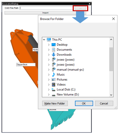
In the dialog window, click the … button.
When the Browse For Folder dialog window appears, specify the path where the file to import exists. (For this tutorial, the file is located in the “<InstallDir>\Help\Tutorial\ProcessNet\General\Excavator\Excavator” directory.)
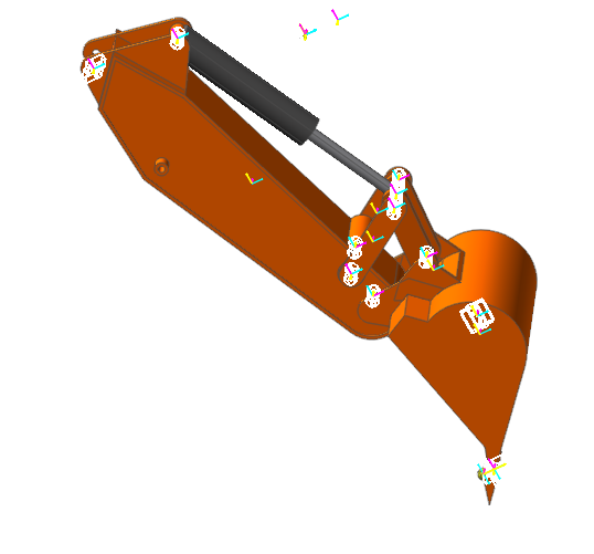
Once you confirm that the file path has been entered in the CAD File Path, click the Import button.
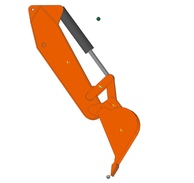
The Excavator model appears automatically, as shown below.
Click the × button in the top right corner of the dialog window to close the ExcavatorDialog window.
Close the ProcessNet Manager dialog window.
2.2.5. Analyzing a Model
2.2.5.1. Task Objectives
In this chapter, you will create a function that applies the values of an entity to the model when the user changes them in the dialog window and learn how to perform model analysis in the dialog window.
2.2.5.2. Estimated Time to Complete this Task
10 minutes
2.2.5.3. Editing the Layout of the Dialog Window
In this section, you will add a text box and a button to the dialog window so that users can perform model analysis and plotting from the dialog window.
2.2.5.3.1. To edit the layout of the dialog window:
In the Project Explorer, double-click ExcavatorDialog.cs. The ExcavatorDialog.cs dialog window appears in the Project Editor pane.
Select the ToolBox, and then add the following controls to the Common Controls list. Then, change the values of these controls.
DialogElement
Text
Name
Location
Size
Button1
Simulation
btSimulation
292, 90
75, 57
Button2
Plot
btPlot
373, 90
75, 57
TextBox1
tbBucketJointAngle
126, 92
154, 20
TextBox2
tbCrankLength
126, 127
154, 20
Label1
BucketJoint_Angle
lbBucketJointAngle
12, 95
83, 12
Label2
Crank_Length
lbCrankLength
12, 130
83, 12
In the File menu, click Save ExcavatorDialog.cs to save the file.
2.2.5.4. Model Analysis Function
In this section, you will create a function that applies the length of a cylinder and the angle of a bucket to the model when a user enters these values in the dialog window. The code will then perform the model analysis when the user clicks the relevant button.
2.2.5.4.1. Model analysis function
In the Project Explorer, double-click PnetFunction.cs.
Under the Import() function created in the previous chapter, create a simulation function.
Enter the following code to change the PV values of PV_DeltaCrankLength and PV_BucketJointAngleDeg using the Bucket Joint Angle and Crank Length values in the dialog window.
public void Simulation(double[] dPVValue)
{
    modelDocument = application.ActiveModelDocument;
    model = modelDocument.Model;

    IParametricValue PV_DeltaCrankLength = model.GetEntity("PV_DeltaCrankLength") as IParametricValue;
    IParametricValue PV_BucketJointAngleDeg = model.GetEntity("PV_BucketJointAngleDeg") as IParametricValue;
    PV_BucketJointAngleDeg.Value = dPVValue[0];
    PV_DeltaCrankLength.Value = dPVValue[1];
    model.Redraw();

    modelDocument.ModelProperty.DynamicAnalysisProperty.SimulationStep.Value = 400;
    modelDocument.ModelProperty.DynamicAnalysisProperty.SimulationTime.Value = 4;
    modelDocument.Analysis(AnalysisMode.Dynamic);
}
In the Project Explorer, right-click ExcavatorDialog.cs, and then click View Designer.
In the function created by double-clicking the Simulation button, enter the following code.
private void btSimulation_Click(object sender, EventArgs e)
{
    double dAngle = Convert.ToDouble(this.tbBucketJointAngle.Text);
    double dLength = Convert.ToDouble(this.tbCrankLength.Text);
    double[] dPVVAlue = new double[] { dAngle , dLength};
    Function.Simulation(dPVVAlue);
}
In the File menu, click Save ExcavatorDialog.cs to save the file.
2.2.6. Creating a Plot Automatically
2.2.6.1. Task Objectives
In this chapter, you will learn the commands used to draw a plot in ProcessNet.
2.2.6.2. Estimated Time to Complete this Task
10 minutes
2.2.6.3. Plot Function
2.2.6.3.1. To use the plot function:
In the Project Explorer, double-click PnetFunction.cs.
Under the Simulation() function created in the previous chapter, create the following Plot function.
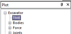
For GetPlotData, “EXCAVATOR” is the root of the plot. This root may differ depending on the RecurDyn version.
Use the ActivateView function to specify the view.
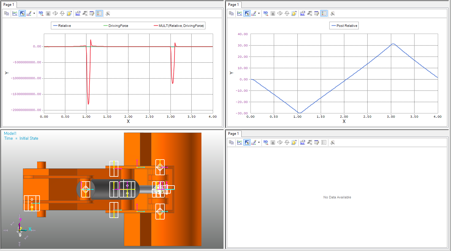
public void Plot()
{
    modelDocument = application.ActiveModelDocument;
    plotDocument = modelDocument.CreatePlotDocument(PlotDocType.WithRPLT);

    double[] Time = plotDocument.GetPlotData("EXCAVATOR/TIME");
    double[] dRelative = plotDocument.GetPlotData
    ("EXCAVATOR/Joints/TraJoint1@HydraulicCylinder/Pos1_Relative");
    double[] dDrivingForce = plotDocument.GetPlotData
    ("EXCAVATOR/Joints/TraJoint1@HydraulicCylinder/Driving_Force");
    double[] dPos1_Relative = plotDocument.GetPlotData
    ("EXCAVATOR/Joints/Rev_Dipper_Bucket/Pos1_Relative");

    plotDocument.PlotShowWindowType(ShowWindowOption.ShowAll);
    plotDocument.LoadAnimation(PlotWindowPosition.LeftLower);

    plotDocument.ActivateView(0, 0);
    plotDocument.DrawPlot("Relative", Time, dRelative);
    plotDocument.DrawPlot("DrivingForce", Time, dDrivingForce);
    plotDocument.SimpleMathMultiply(0, 1, false, true);

    plotDocument.ActivateView(0, 1);
    plotDocument.DrawPlot("Post Relative", Time, dPos1_Relative);
}
In the Project Explorer, right-click ExcavatorDialog.cs, and then click View Designer.
Double-click the Plot button.
Under the created function, enter the following Plot function.
private void btPlot_Click(object sender, EventArgs e)
{
    Function.Plot();
}
In the File menu, click Save ExcavatorDialog.cs to save the file.
2.2.6.4. Testing the Created Application
In this section, you will test whether the application you created works properly.
2.2.6.4.1. To run the application:
In the Build menu, click Build Solution. Check if any errors or warnings appear in the Error List pane at the bottom of the IDE window. If there are any errors or warnings, correct the problems.
In RecurDyn, on the Customize tab, in the ProcessNet(General) group, click the Run function.
In the tree in the lower half of the ProcessNet Manager dialog window, click Run under Excavator.
In the ProcessNet Manager dialog window, click Run. The dialog window shown on the below appears.3
In the dialog window, type 0 for both the BucketJoint_Angle and Crank_Length.
Click the Simulation button to confirm that the PV_DeltaCrankLength and PV_BucketJointAngleDeg values change according to the BucketJoint_Angle and Crank_Length values you entered and that the model analysis is performed according to the new values.
Once the analysis is complete, click the Plot button to draw a plot shown below.
Close the ExcavatorDialog window.
Close the ProcessNet Manager dialog window.