9.3. Planet Gear Tutorial (Gear)
9.3.1. Getting Started
9.3.1.1. Objective
In this tutorial, you will simulate some simple gear systems to become familiar with the RecurDyn/Gear Toolkit. The first system will be a planetary gear set using spur gears. The effect of misaligning one of the gears will be studied. The second system will be two gear pairs, one using spur gears and the other using helical gears. This system will be used to compare the performance of the two different gear types.
9.3.1.2. Audience
This tutorial is intended for intermediate users of RecurDyn who previously learned how to create geometry, joints, and force entities. All new tasks are explained carefully.
9.3.1.3. Prerequisites
You should first work through the 3D Crank-Slider and Engine with Propeller tutorials, or the equivalent. We assume that you have a basic knowledge of physics.
9.3.1.4. Procedures
The tutorial is comprised of the following procedures. The estimated time to complete each procedure is shown in the table.
Procedures |
Time (minutes) |
Creating the Planetary Gear Set Model |
20 |
Studying Misalignment Effects |
15 |
Helical Gears |
20 |
Total |
55 |
9.3.1.5. Estimated Time to Complete
55 minutes
9.3.2. Creating the Planetary Gear Set model
9.3.2.1. Task Objective
Learn how to create a simple gear system.
9.3.2.2. Estimated Time to Complete
20 minutes
9.3.2.3. Creating a New Model and Gear Subsystem
9.3.2.3.1. To create a new model:
On your Desktop, double-click the RecurDyn tool. RecurDyn starts and the Start RecurDyn window appears.
Enter PlanetaryGearSet as the Model Name.
Select OK.
9.3.2.3.2. To create a new gear subsystem:
From Render Toolbar, select the Wireframe tool.

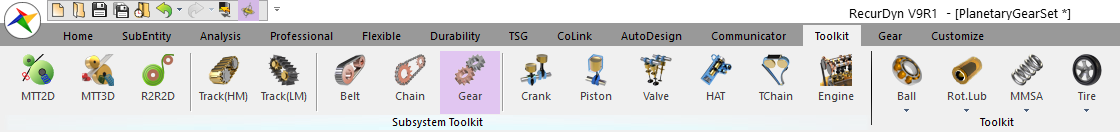
From the Subsystem Toolkit group in the Toolkit tab, click the Gear function.
RecurDyn will bring you into the new Gear subsystem, and a new Gear tab will appear in the ribbon.
9.3.2.4. Customizing Settings
You will now make some custom settings to the program and to the model. You will improve the graphic display of the model and results, and you will turn off the shift when Pasting option to make the future modeling steps easier.
9.3.2.4.1. To improve the graphic display of the model and results:
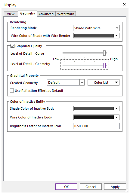
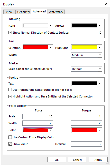
From Setting group in the Home tab, click the Display Setting function. The Display dialog will be shown.
Check the box next to Graphical Quality in the Geometry page.
Adjust the two slider bars to the below to improve the display quality.
Select the Advanced page.
Under Force, make the following settings:
Scale: 10
And, in the Color page, Under Force, make the following settings:
Color: Red
9.3.2.4.2. To turn off Shift When Pasting
From Setting group in the Home tab, click the General Setting function.
Deselect the checkbox next to Shift when Pasting.
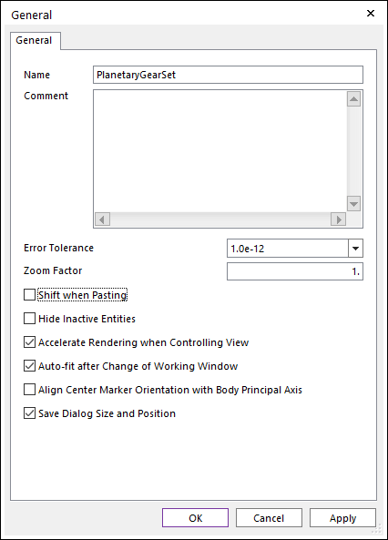
Click OK.
9.3.2.5. Creating the Gears
9.3.2.5.1. To create the sun gear:
From the Gear group in the Gear tab, click the Spur Gear function.
Select the point 0, 0, 0 in the Working window to define the center of the gear or type the values into in the Input windows toolbar. The SpurGear dialog will appear.
Select the Geometry Data page.
Set the Number of Teeth to 30.
Click Generate optimal arc segment.
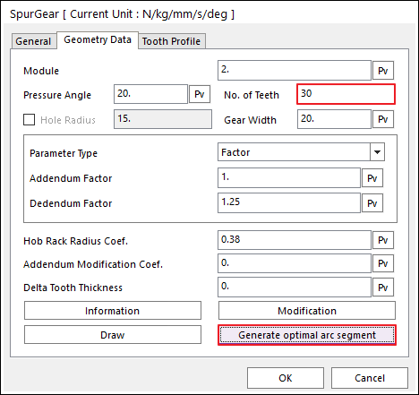
Click OK.
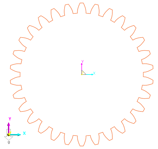
In the Database Window, right-click on SpurGear1.
Select Rename.
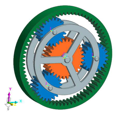
Rename the gear to SunGear. The model should now appear as shown below.
9.3.2.5.2. To create the planet gears:
Repeat the steps above to create another spur gear, this time with 21 teeth, and named PlanetGear1.
In the Working window, select PlanetGear1, the gear you just created.
Type Ctrl+C key to copy the gear.
Type Ctrl+V key two times to create two more planet gears. You will move them to their correct location later.
Rename the other two planet gears to PlanetGear2, and PlanetGear3 using the Database Window rename capability.
9.3.2.5.3. To create the outer ring gear:
From the Gear group in the Gear tab, click Int.Spur.
Select the point 0, 0, 0 in the Working window to define the center of the gear. The SpurGearInternal1 dialog will appear.
Select the Geometry Data page.
Make the following settings, as shown at below.
Number of Teeth: 72
Outer Diameter: 160
Select Generate optimal arc segment.
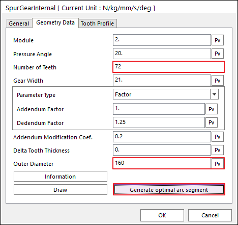
Select OK.
Rename the gear to OuterRingGear. Your model should now appear as shown at below.
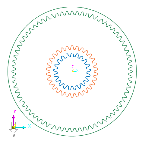
9.3.2.6. Arranging the Gears
You will now move the planet gears into position so that their teeth engage correctly with the sun gear.
9.3.2.6.1. To engage the first planet gear:
From View Control Toolbar, select the Grid On/Off tool to turn the grid display on.

From the Working Plane group in the Home tab, change the Coordinate from Car (Cartesian) to Cyl (Cylindrical), as shown at below.
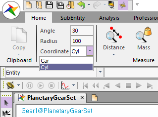
This will change the grid display as shown at right, so you can easily select points exactly at 120° and 240° from the center of the sun gear.
Change the Radius to 10.
From the Assembly group in the Gear tab, click the Assembly function.
In the Working window, select SunGear as the base gear.
To select the action gear, in the Working window, right-click on the planet gears, and select Select List, as shown at below.
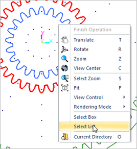
A list of selectable entities will be brought up.
Select PlanetGear1 from the list and click OK.
For the Center Distance, enter 51.
Click Auto Engagement.
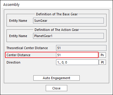
Click Close.
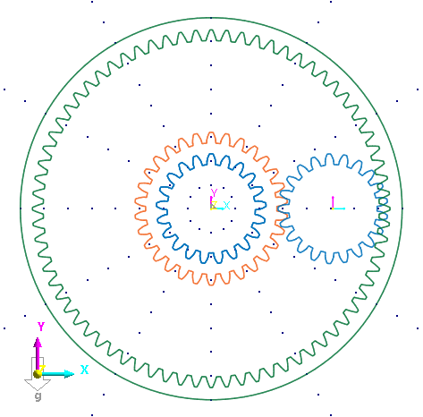
Your model should now appear as shown below.
9.3.2.6.2. To engage the remaining two planet gears:
The assembly process, this time selecting PlanetGear2 as the action gear.
This time, in the Assembly dialog, to the right of Direction, select Pt.
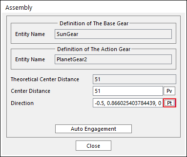
In the Working Window, select any grid point along the 120° line.
Again, select Auto Engagement and Close to move PlanetGear2 into place at 120° from the sun gear.
Repeat the assembly process for PlanetGear3, selecting any grid point along the 240° line.
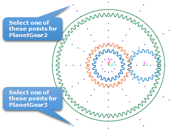
The model should now appear as shown below.
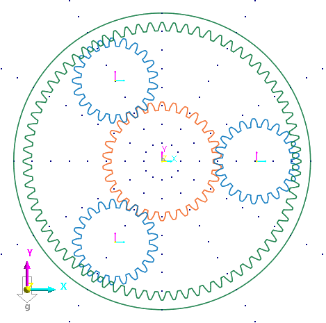
At this point, the outer ring gear should look correctly sized to mesh with the planet gears, however, the angle of the gear is off by half a gear tooth, or ½ × 360° / 72 teeth = 2.5°. You will now rotate the outer ring gear by that amount to align it correctly with the planet gears.
9.3.2.6.3. To align the outer ring gear:
Select the OuterRingGear.
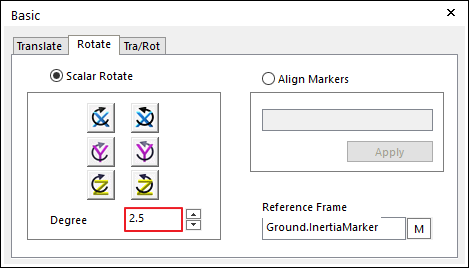
From View Control Toolbar, select the Basic Object Control tool.

Select the Rotate page.
Enter an angle of 2.5 degrees.
Click the Counterclockwise about Z- axis button.
Close the Basic Object Control dialog.
The outer ring gear teeth should now align with those of the planet gears.
9.3.2.7. Importing the Planet Gear Holder Geometry
You will now import geometry representing the planet gear holder.
9.3.2.7.1. To import the planet gear holder:
From the File menu, select the Import function. The Import dialog will appear.
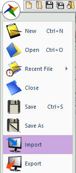
Change the file type to ParaSolid File(*.x_t;*.x_b;*.xmt;*.xmt_bin).
- Navigate to the Gear Tutorial directory and select the file PlanetGearCarrier.x_t.(The file path: <InstallDir>\Help\Tutorial\Toolkit\Gear\PlanetGear)
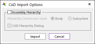
Click Open. The CAD Import Options window appears. Clear the Assembly Hierarchy checkbox and click Import.
Rename the new body, ImportedBody1, to PlanetGearCarrier.
The model should now appear as shown below.
9.3.2.8. Creating the Joints
You will now create several revolute joints to connect the gears to the various bodies. The outer ring gear will be fixed to ground.
9.3.2.8.1. To create the joints:
From the Joint group in the Professional tab, click the Fixed Joint function.
Set the Creation Method to Body, Body, Point.
Select MotherBody as the base body by clicking in the background of the Working window.
Select OuterRingGear as the action body.
Enter 0, 0, 0 in the Input Window Toolbar.
From the Joint group in the Professional tab, click the Revolute Joint function.
Set the Creation Method to Body, Body, Point.
Select MotherBody as the base body.
Select PlanetGearCarrier as the action body.
Enter 0, 0, 0 in the Input Window toolbar.
Repeat Steps 6-10 to create revolute joints between the following bodies (use the center of mass markers to place the revolute joints at the centers of the gears).
Joint
Base Body
Action Body
RevJoint2
MotherBody
SunGear
RevJoint3
PlanetGearCarrier
PlanetGear1
RevJoint4
PlanetGearCarrier
PlanetGear2
RevJoint5
PlanetGearCarrier
PlanetGear3
9.3.2.9. Creating the 2D Contacts
For quick simulations, RecurDyn allows the creation of 2D contacts which take into account the profile shape of the gear teeth. You will now create 2D contacts between the gears.
9.3.2.9.1. To create the 2D Contacts:
From the Contact group in the Gear tab, click the 2D Curve (Curve to Curve Contact) function.
Select SunGear as the base body.
Select PlanetGear1 as the action body.
Repeat Steps 1-4 above to create contacts between the following gears:
Contact
Base Body
Action Body
GearContact2
SunGear
PlanetGear2
GearContact3
SunGear
PlanetGear3
GearContact4
OuterRingGear
PlanetGear1
GearContact5
OuterRingGear
PlanetGear2
GearContact6
OuterRingGear
PlanetGear3
You will now modify the contact parameters to improve simulation speed and improve results for this model.
9.3.2.9.2. To modify the 2D Contact parameters:
In the Database Window, select GearContact1 - GearContact6 by doing the following.
Select GearContact1.
Press and hold down the Shift key.
Select GearContact6.
Right-click on one of the selected entities and select Properties.
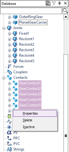
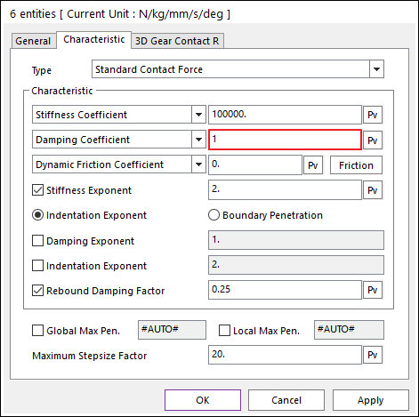
A Properties dialog titled 6 entities will be displayed.
Select the Contact Characteristic page.
Make the following settings.
Stiffness Coefficient: 100000
Damping Coefficient: 1
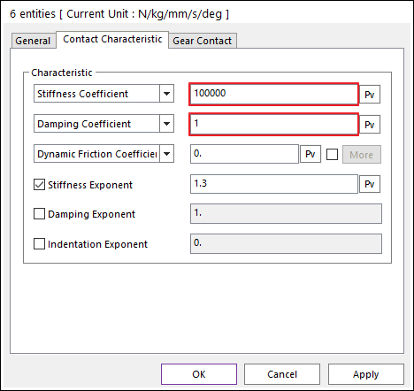
Click OK.
9.3.2.10. Applying a Motion Input and a Torque Load
You will now apply a motion input to the planet gear carrier and apply a resistive torque load onto the sun gear.
9.3.2.10.1. To apply a motion input:
Open the Properties window for RevJoint1, the revolute joint between MotherBody and PlanetGearCarrier.
Select the Include Motion checkbox and click Motion.
Select Velocity from the dropdown menu.
Click EL.
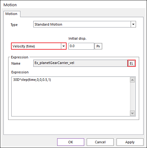
Click Create.
Enter Ex_planetGearCarrier_vel as the expression name.
Enter the following for the expression.
30D*step(time, 0, 0, 0.5, 1)
Click OK four times to exit out of all the dialog windows.
9.3.2.10.2. To apply a resistive torque load:
From the Force group in the Professional tab, click the Rotational Axial Force function.
Set the Creation Method to Joint.
Use the Select List to select RevJoint2, the revolute joint between MotherBody and SunGear.
Open the Properties dialog for RotationalAxial1.
Click EL.
Click Create.
Enter Ex_sunGear_resistTorque for the expression name.
Enter -100 as the expression.
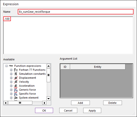
Click OK three times.
Construction of the model is now complete, and simulations can be run.
9.3.2.11. Running a Simulation
You will now simulate the model and verify the observed gear ratio between the planet gear carrier and the sun gear.
9.3.2.11.1. To run a simulation:
From the Simulation Type group in the Analysis tab, click the Dynamic / Kinematic Analysis function.
Make the following changes.
End Time: 4
Step: 200
Plot Multiplier Step Factor: 5
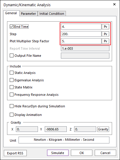
Click Simulate.
When the simulation finishes, you can play the animation by clicking the Play tool in Animation Toolbar.
The animation should show the planetary gear system working smoothly with no problems.
9.3.3. Studying Misalignment Effects
9.3.3.1. Task Objective
Observe how misaligning one of the planet gears affects the planetary gear system.
9.3.3.2. Estimated Time to Complete
15 minutes
9.3.3.3. Switching to 3D Contacts
Because you will be misaligning one of the gears, using the 2D contacts is no longer valid since you want to study the non-ideal behavior of the system caused by 3D interactions between the gears. Therefore, the first step is to create new 3D gear contacts and deactivate the 2D contacts.
9.3.3.3.1. To create the 3D gear contacts:
From the Contact group in the Gear tab, click the 3D Contact R (Solid Contact) function.
Select SunGear as the base body.
Select PlanetGear1 as the action body.
Repeat Steps 1-3 above to create contacts between the following gears.
Contact
Base Body
Action Body
GearContact3DR2
SunGear
PlanetGear2
GearContact3DR3
SunGear
PlanetGear3
GearContact3DR4
OuterRingGear
PlanetGear1
GearContact3DR5
OuterRingGear
PlanetGear2
GearContact3DR6
OuterRingGear
PlanetGear3
You will now modify the contact parameters to improve simulation speed and improve results for this model.
9.3.3.3.2. To modify the 3D Contact parameters:
In the Database Window, select GearContact3DR1 - GearContact3DR6, using the Shift key as done before.
Right-click on one of the selected entities and select Properties. A Properties dialog titled 6 entities will be displayed.
Under the 3D Gear Contact R page, set No. of Max Contact Points to 10.
Set the Force Display to Action.
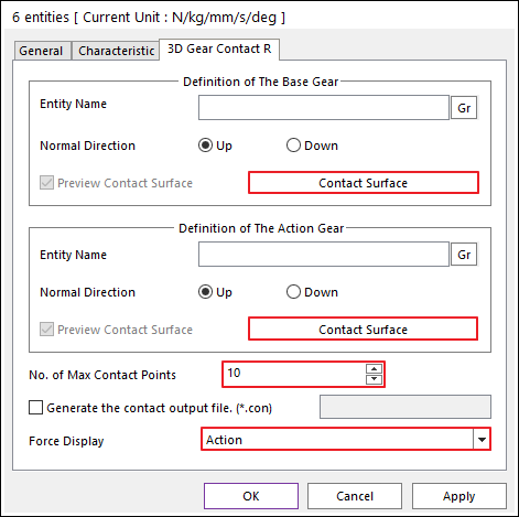
In the Base Gear section, click Contact Surface.
Set the Plane Tolerance Factor to 1.
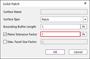
Click OK.
Repeat Steps 5-6 above for the Action Gear.
Select the Characteristic page.
Change the Damping Coefficient to 1.
Click OK.
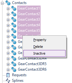
9.3.3.3.3. To deactivate the 2D gear contacts:
In the Database Window, select GearContact1 - GearContact6.
Right-click and select Inactive.
9.3.3.4. Simulating and Viewing the 3D Contact Results
Before misaligning one of the gears, you will simulate the aligned case with 3D contacts which you will be able to use as a case to compare the misaligned case with.
9.3.3.4.1. To simulate and view the results:
Simulate the model as done before.
When the simulation is done, play the animation results.
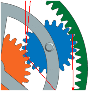
The results should appear as shown below, with the contact force arrows appearing evenly distributed between all three planet gears. The contact force arrows should transition from tooth to tooth as the gears turn.
9.3.3.5. Misaligning a Planet Gear
You will now save the model under a different name and then misalign the planet gear on the right side.
9.3.3.5.1. To misalign a planet gear:
From the File menu, select the Save As function.
Save the model as PlanetaryGearSet_misaligned.rdyn.
In the Database Window, right-click on PlanetGear1, and select Edit.
You should now be in the body edit mode of PlanetGear1.
From the Database Window, select SpurGear1.
From Advanced Toolbar, select the Basic Object Control tool.
Select the Rotate page.
Enter an angle of 0.5 degrees.
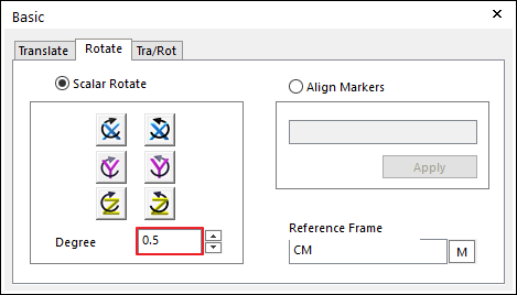
Click the Counterclockwise about Y-Axis button.
Close the Basic Object Control dialog.
From the Quick Access Toolbar, select the Exit tool to exit the body edit mode and return to the gear subsystem.
9.3.3.6. Simulating the Misaligned Model and Comparing Results
You will now simulate the model and then compare the results to those of the ideal model.
9.3.3.6.1. To simulate the model:
Simulate the model as before, changing the End Time to 4 sec if needed.
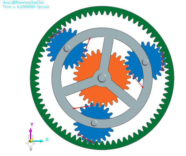
When the simulation is complete, play back the animation results.
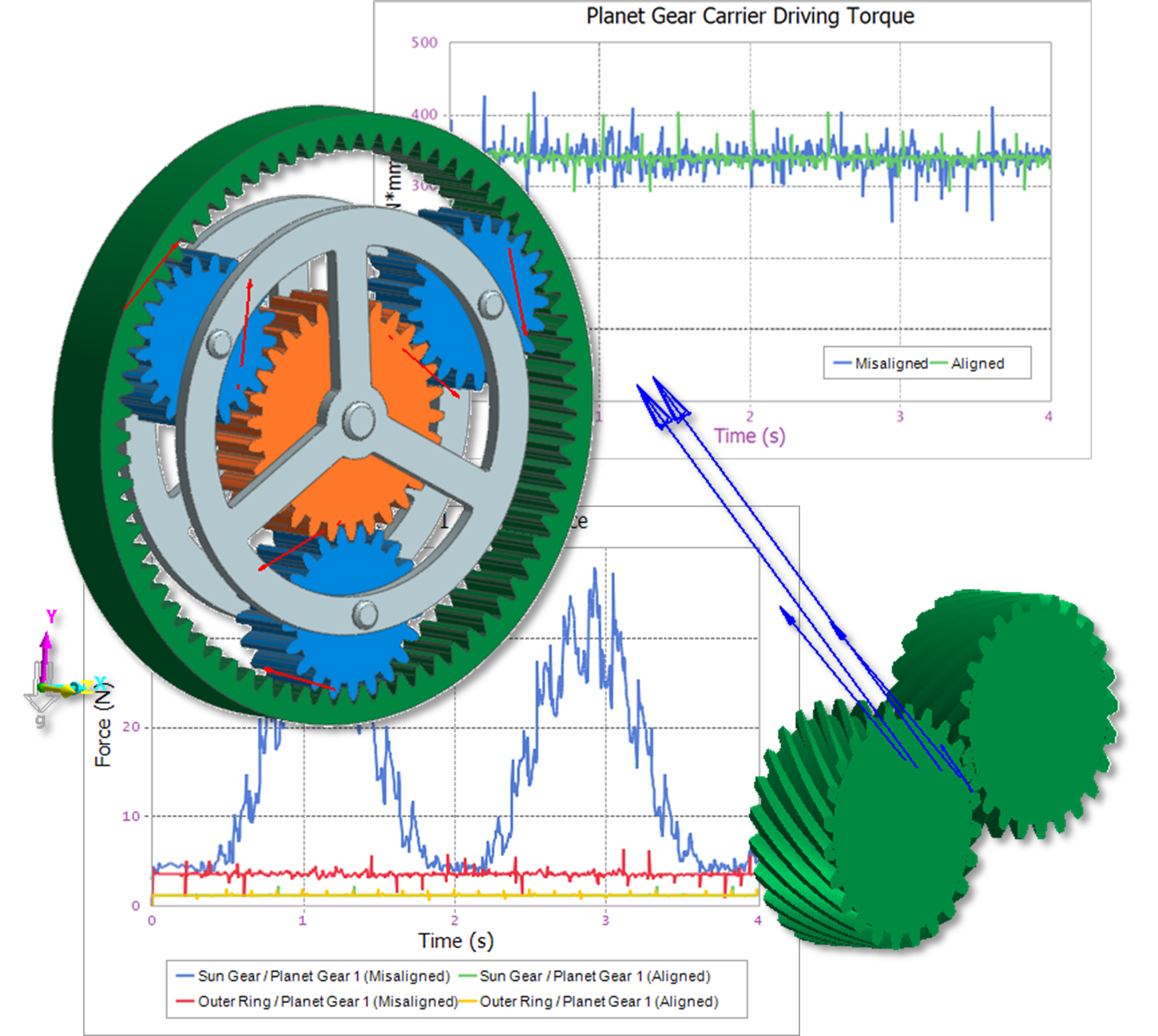
You should see, as shown below, that the gear tooth contact forces become very high at certain points of the simulation depending on the orientation of the misaligned gear with respect to the sun and outer ring gears.
9.3.3.6.2. To compare the results:
From the Plot group in the Analysis tab, click the Plot Result function. The plotting environment will be opened.
From the Import group in the Home tab, click the Import File function.
Select the file PlanetaryGearSet.rplt and click OK.
To plot the driving torque of RevJoint1 for both sets of data.
Right-click on PlanetaryGearSet_misaligned -> Joints -> RevJoint1 -> Driving_Torque.
Click Multi Draw.
There should be an initial negative spike in the plot which will cause the y-axis scale to be too large.
9.3.3.6.3. To adjust the y-axis scale:
Right-click on one of the y-axis number labels and select Properties.
Make the following settings, as shown at below.
Step: 100
Minimum: 0
Maximum: 500
Decimals: 0
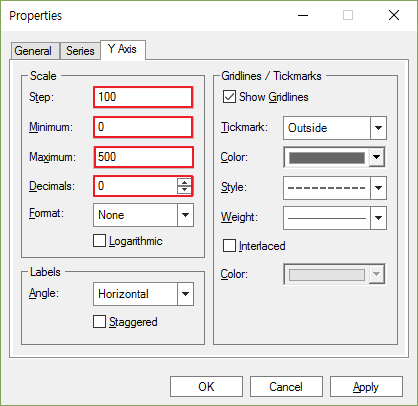
- Click OK.The plot should now appear similar to the one shown below. While both curves show periodic fluctuation with the frequency at which the gear teeth mesh, the driving torque for the misaligned model is noisier and also shows more fluctuation during the times when the misalignment has its greatest effect.
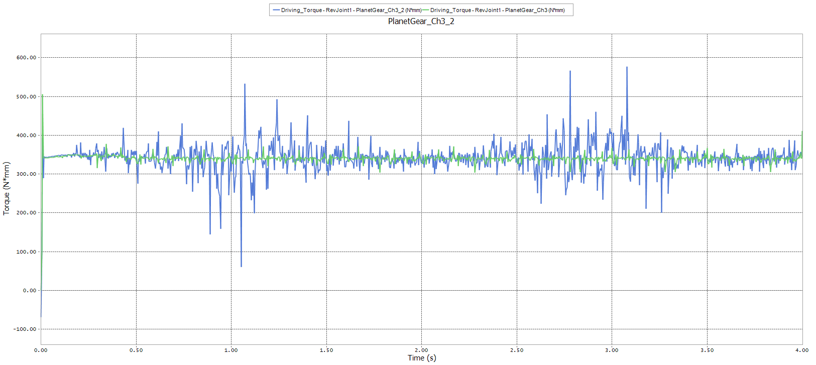
From the Page group in the Home tab, click the Add Page function.
Repeat the steps above to plot the following data for both models.
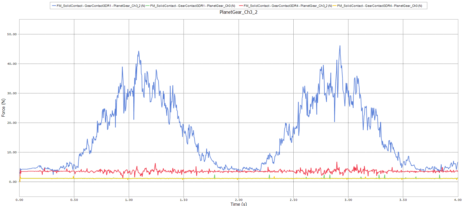
Contact -> Solid Contact -> GearContact3DR1 -> FM_SolidContact (contact between the sun gear and planet gear 1)
Contact -> Solid Contact -> GearContact3DR4 -> FM_SolidContact (contact between the outer ring gear and planet gear 1)
The plot should appear similar to the one shown below. Here, the periodic increase in contact force for the misaligned model can be seen easily, while the contact force for the aligned model is relatively constant.
9.3.4. Helical Gears
9.3.4.1. Task Objective
Helical gears are often used in place of spur gears when noise reduction and smoothness of operation are of concern. In this chapter you will learn to create a helical gear pair and compare its performance with an equivalent spur gear pair.
9.3.4.2. Estimated Time to Complete
20 minutes.
9.3.4.3. Creating the Model
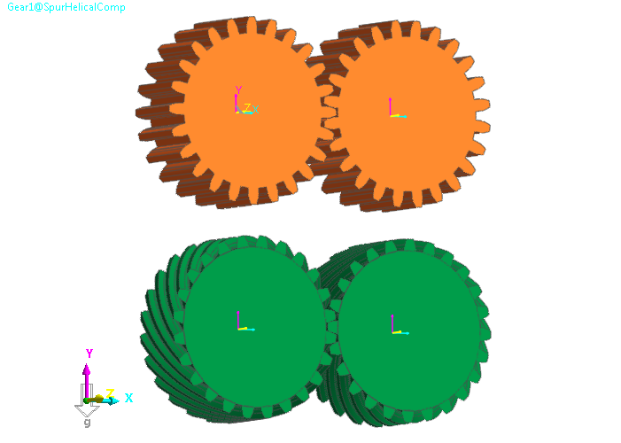
You will now create a model which will contain both a helical and a spur gear pair. When you are done with this set of steps, the model should appear as shown below.
9.3.4.3.1. To create the spur gears
Create a new model, naming it SpurHelicalComp.
Create a gear subsystem within the new model.
From the Gear in the Gear tab, click the Spur Gear function.
Select the point 0, 0, 0 as the gear center.
Select the Geometry Data page.
Set the Pressure Angle to 15.
Click Generate optimal arc segment.
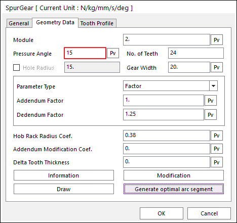
Click OK.
Make a copy of the above gear and translate it 50 mm in the +X direction.
Use the Assembly tool to mesh the gears with centers at 48mm apart.
9.3.4.3.2. To create the helical gears
From the Gear group in the Gear tab, click the Helical Gear function.
Select the point 0, -60, 0 as the gear center.
Make the following settings, as shown at below.
Module: 1.414
Pressure Angle: 15
Helix Angle: 45
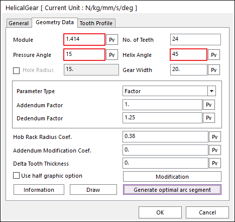
Note
To obtain a helical gear that is the same size as an equivalent spur gear, the module should be:
\(\text{module}_{\text{helical}} = \text{module}_{\text{spur}} \bullet cos(helix\ angle)\)
Click Generate optimal arc segment.
Click OK.
Make a copy of the gear you just created and translate it 50**mm in the **+X direction.
Open the Properties dialog for the gear you just copied.
Under the Geometry Data page, change the Helix Angle to -45. In order for helix gears lying in the same plane to mesh, the helix angles must be of equal magnitude and opposite sign.
Click OK.
Use the Assembly tool to mesh the gears with centers at 48 mm apart.
9.3.4.3.3. To finish and simulate the model
Create four revolute joints at the centers of the gears in the following order (specifying MotherBody as the base bodies and the gears as the action bodies).
Joint
Gear Body
RevJoint1
SpurGear1
RevJoint2
C1_SpurGear1
RevJoint3
HelicalGear1
RevJoint4
C1_HelicalGear1
Create the following expression, naming it Ex_drivGearDrive_vel.
600D*step(time, 0, 0, 0.5, 1)
Assign this as the driving expression for the velocity of RevJoint1 and RevJoint3.
Create two RotationalAxial forces applied at RevJoint2 and RevJoint4.
Create the following expression, naming it Ex_resistTorque.
1000
Assign the above expression to the two RotationalAxial forces.
Create two Involute Analytic Contact contacts, one for the Spur gears and one for the Helical gears. Modify the contact settings as before, by making the following changes:
Force Display: Action
Simulate the model, using the following settings.
End Time: 1
Step: 200
Plot Multiplier Step Factor: 5
When the simulation stops, play the results animation. You should see from the contact force arrows that the contact points travel in a curved path from the front (+Z side) of the gear to the back (-Z side), as shown below.
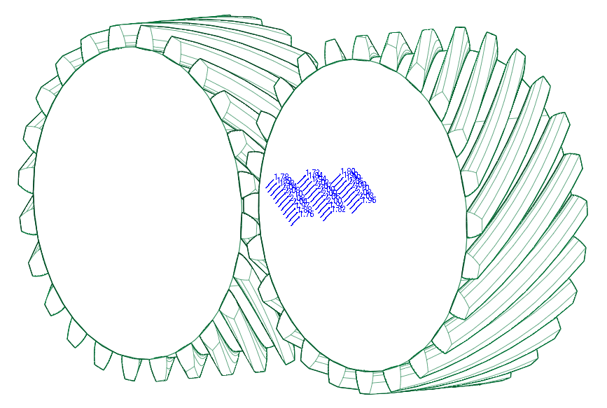
To understand what is happening in more detail, you can turn off the display of the helical gear on the right side.
In the Render Toolbar, select the Render Each tool.
In the Database Window, right-click on HelicalGear1, and select Shade.
In the Database Window, right-click on C1_HelicalGear1, and select Hide.
You should now be able to see, as shown at below, that each contact point is between its own pair of teeth, and that with the given gear specifications, four gear teeth pairs are always in contact. Each contact points begin at the front (+Z) end of the gear tooth face and advances backwards to the other (-Z) end of the gear tooth face at which point that particular pair of gear teeth is no longer in contact. This sliding nature of the contact points, as well as the distribution of contact over four points, is why helical gears are quieter and operate more smoothly than spur gears.

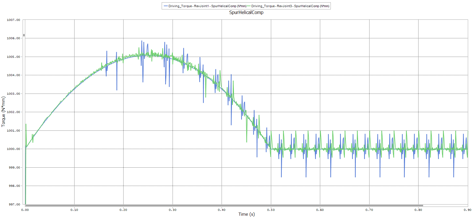
9.3.4.3.4. To compare the driving torque results
Open the plotting environment.
Plot the driving torque for RevJoint1 and RevJoint3.
Joints -> RevJoint1 -> Driving_Torque
Joints -> RevJoint3 -> Driving_Torque
You should see a plot similar to the one below. The plot indicates that the driving torque is slightly smoother for the helical gear than the spur gear. The plot below is the zoomed result.
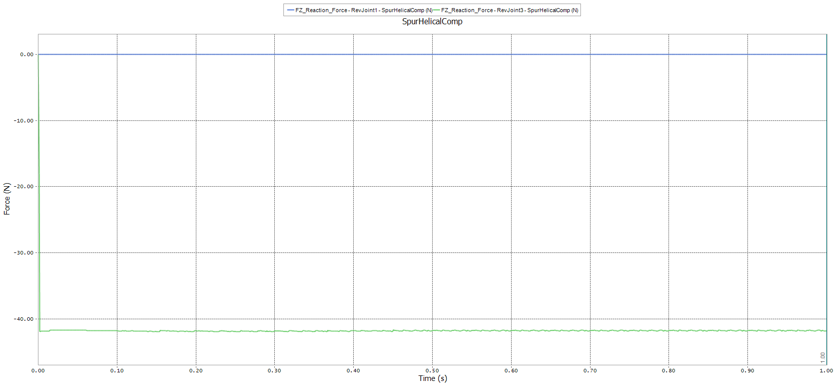
Plot the force in the Z direction exerted by ground on the driving gears:
Joints -> RevJoint1 -> FZ_Reaction_Force
Joints -> RevJoint3 -> FZ_Reaction_Force
You should see a plot similar to the one shown below. This plot reveals one disadvantage of using helical gears, which is that due to the angle that the gear tooth faces are set at (the helix angle), an axial thrust is generated. This requires that special bearing be used which can withstand the axial load.