10.3. Cleated Belt Conveyor (EDEM)
10.3.1. Overview
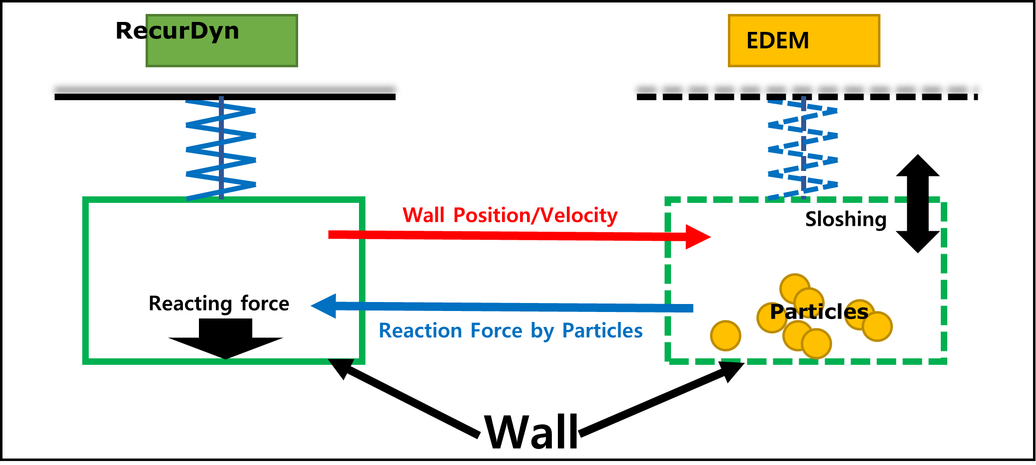
This tutorial covers how to perform co-simulation between the two software RecurDyn and EDEM. RecurDyn covers kinematic analysis and flexible body analysis, and EDEM the particle analysis using DEM (discrete element modeling). This tutorial will analyze the behavior of particles according to the movement of a flexible body, using the two software.
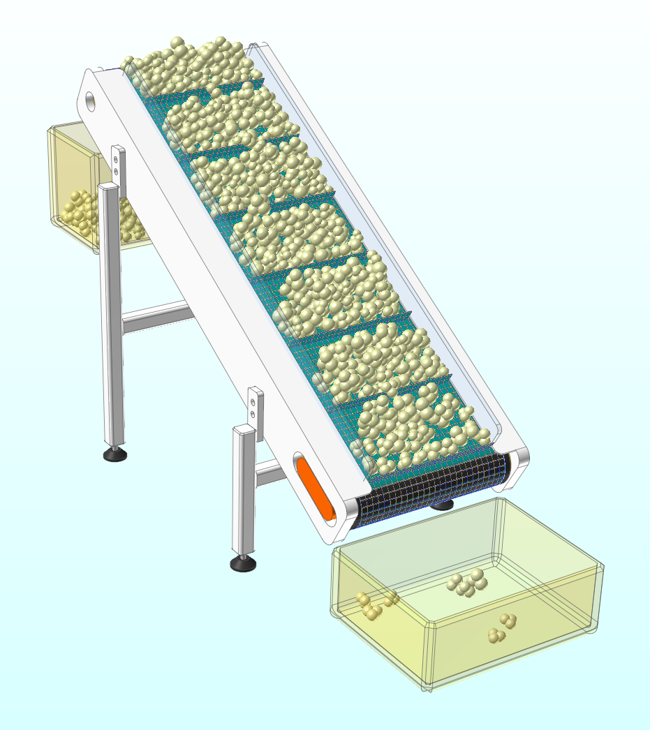
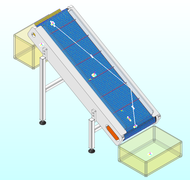
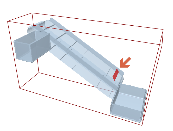
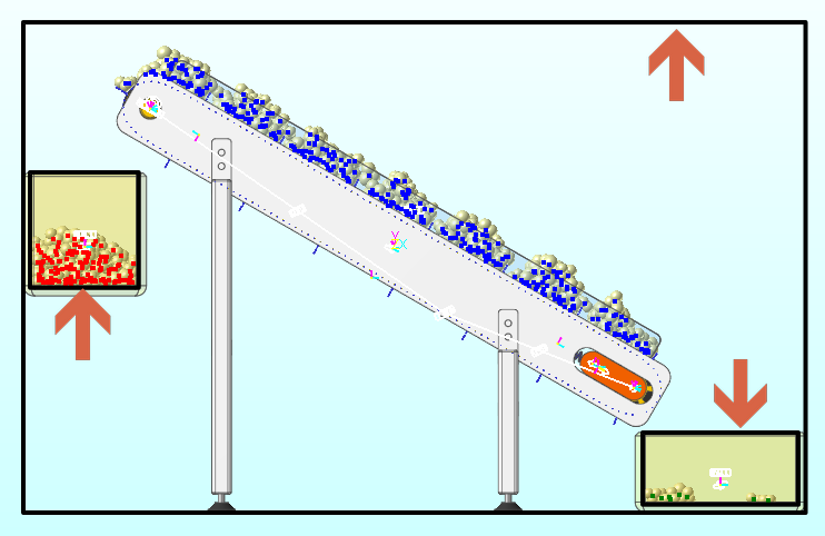
The model to be covered in this tutorial is a cleated belt conveyor system, which transports the particles coming in at a constant speed upwards along the slope. We will try to figure out the velocity of the belt or the inflow of the particles that ensures maximum efficiency without losing the particles.
10.3.1.1. Task Objectives
This tutorial covers the following topics:
How to create walls for a rigid body and a flexible body through RecurDyn
How to export a wall through RecurDyn
How to find properties in EDEM
How to create particles in EDEM
How to perform co-simulation in RecurDyn
How to perform post-processing in RecurDyn and EDEM
10.3.1.2. Prerequisites
This tutorial is intended for users who have completed the basic tutorials provided with RecurDyn. If you have not completed these tutorials, then you should complete them before proceeding with this tutorial.
The EDEM software must be installed to proceed with this tutorial. This tutorial was created based on the version EDEM 2019.
10.3.1.3. Procedures
This tutorial consists of the following tasks. The following table outlines the time required to complete each task. (* The time required may vary depending on the specifications of the computer and the proficiency of the user.)
Procedures |
Time (minutes) |
Registering EDEM GUI on the RecurDyn ribbon |
5 |
Simulating and analyzing the initial model |
15 |
Creating and exporting a wall |
5 |
Creating an EDEM model |
10 |
Co-simulation |
150 |
Analyzing and reviewing the results |
10 |
Total |
195 |
10.3.2. Registering EDEM GUI on the RecurDyn Ribbon
The RecurDyn Ribbon GUI does not show the External SPI (EDEM) GUI by default. You must add the GUI to RecurDyn using the Configuration XML file provided separately.
10.3.2.1. Task Objectives
In this chapter, you will learn how to add the External SPI (EDEM) tab to the GUI on the RecurDyn Ribbon using the Configuration XML file provided by the EDEM software.
10.3.2.2. Estimated Time to Complete This Task
5 minutes
10.3.2.3. Importing the Configuration XML File
10.3.2.3.1. To copy the EDEMV1_1_0.xml file:
10.3.2.3.2. To paste the file into the RecurDyn folder:
10.3.2.3.3. To check the RecurDyn GUI:
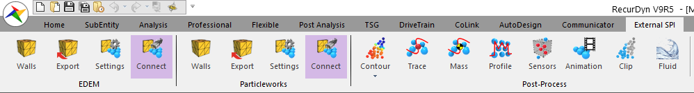
When you run RecurDyn, you will see that an External SPI tab was created in the ribbon GUI as shown below and an EDEM group was created in the submenu.
10.3.2.3.4. To check the path of Particle Solver DLL:
Check the path where the Particle Solver DLL file should be present.
In the EDEM group of the External SPI tab, click the Settings function.
When the dialog window appears, click Info.
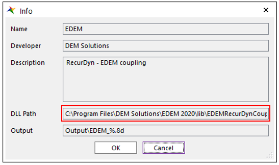
You can check the DLL Path in the Info dialog window. This path is set to the default installation location of EDEM. So, if you installed EDEM in a different path, you must modify the DLL path in the Configuration XML file.
Tip
Modifying the Particle Solver DLL path in Configuration XML file (Perform it when the DLL path in the Info dialog window is different from the EDEM installation path.)
Open the EDEMV1_1_0.xml file.
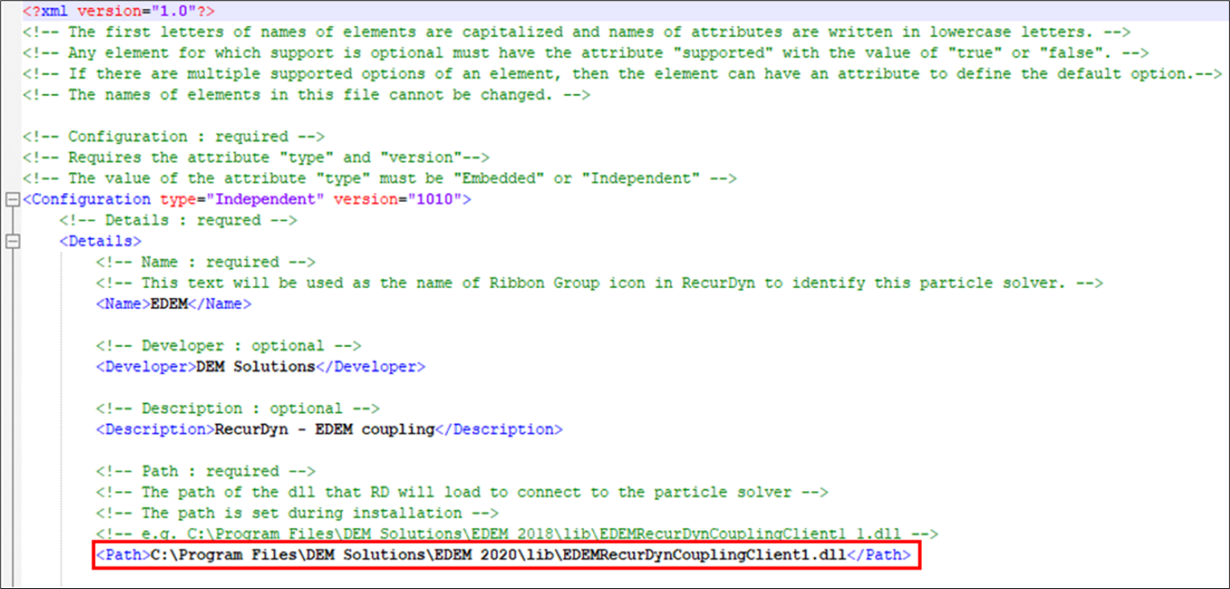
Modify the DLL path following <Path> as shown below.
Save the Configuration XML file.
After confirming that the Configuration XML has been modified successfully, restart RecurDyn.
10.3.3. Simulating and Analyzing the Initial Model
This tutorial provides a complete cleated belt conveyor model. Before proceeding with ED configuration EM and co-simulation, we will simulate the MFBD model alone in RecurDyn and analyze the model.
10.3.3.1. Task Objectives
In this chapter, you will simulate and analyze the cleated belt conveyor model provided by RecurDyn.
10.3.3.2. Estimated Time to Complete This Task
15 minutes
10.3.3.3. Opening the Model
10.3.3.3.1. To copy the example model:
- Copy the SPI (EDEM) tutorial example folder provided by RecurDyn to an analyzable location.Folder path: <InstallDir>\Help\Tutorial\SPI\EDEM\CleatedBeltConveyor
10.3.3.3.2. To run RecurDyn and open the initial model:
On the Desktop, double-click the RecurDyn icon to run RecurDyn. The Start RecurDyn dialog window will appear.
When the Start RecurDyn dialog window appears, close it.
In the File menu, click the Open function.
In the CleatedBeltConveyor folder copied above, select CleatedBeltConveyor_Start.rdyn.
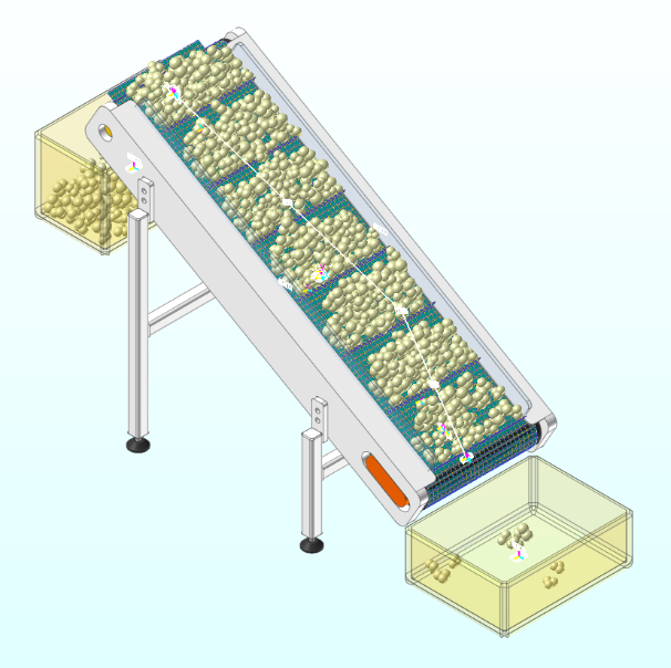
Click Open. The model appears as shown in the following figure.
10.3.3.3.3. To analyze the model configuration:
Click the Layer Settings tool in the Render Toolbar.
In the Layer Settings dialog window, turn on and off each layer to analyze the model.
The following explains the configuration of the model.
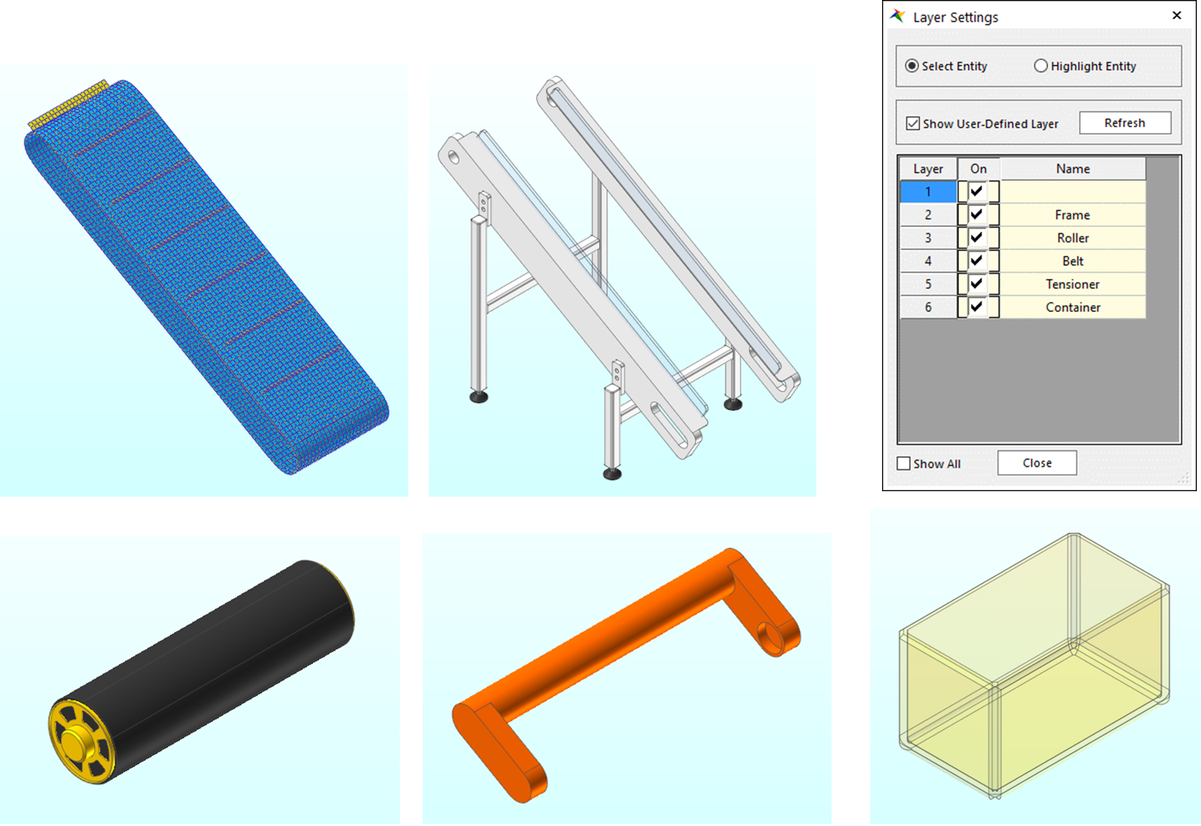
The model consists of a belt, frame, roller, tensioner, and container. Here, the belt is modeled as a flexible body. The belt and roller consist with geo cylinder contacts and the roller is rotated by motion.
10.3.3.4. Performing Simulation
Run the simulation to help you understand the model system.
10.3.3.4.1. To run the simulation:
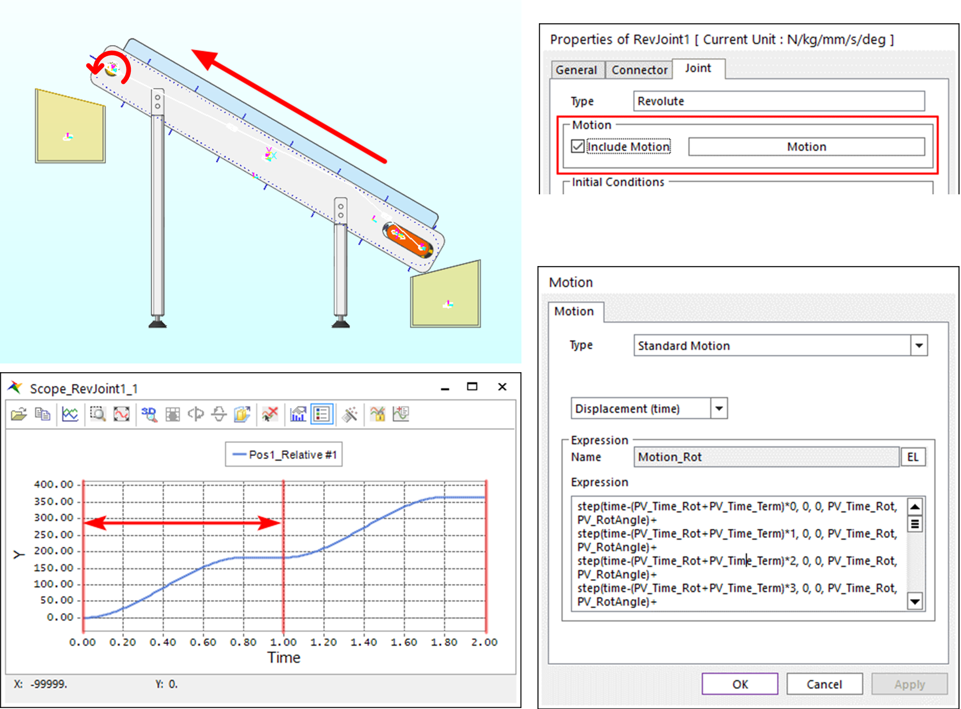
On the Analysis tab, in the Simulation Type group, click the Dynamic/Kinematic Analysis function. The Dynamic/Kinematic Analysis dialog window appears.
After verifying the simulation conditions, click Simulate.
End Time: 2
Step: 200
10.3.3.4.2. To view the result:
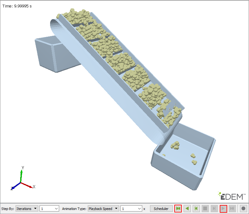
Under the Analysis tab, in the Animation Control group, press the Play function to check if the system operates as shown in the figure below.
The belt moves by the motion of RevJoint1, which is attached to the upper roller. If you plot the scope for Pos1_Relative of RevJoint1, you can see that it rotates constantly at a cycle of 1 second.
10.3.4. Creating and Exporting a Wall
RecurDyn and EDEM need a medium called wall to exchange data with each other.
10.3.4.1. Task Objectives
In this chapter, you will learn how to define the geometry to import from EDEM in RecurDyn and how to export *.wall files.
10.3.4.2. Estimated Time to Complete This Task
5 minutes
10.3.4.3. Creating walls
Note
To define a flexible body as a wall, you must define a face to be a wall as a patch set.
10.3.4.3.1. To create PatchSet:
Enter the Flex Edit Mode of Shell_CleatedBelt.
In the Set group of the FFlex Edit tab, click the Patch Set function.
Click Add/Remove in the Patch Set dialog window.
Select all the patches.
Right-click the working window and click Finish Operation in the pop-up menu.
After verifying if No. of Patches are 5340 and click OK to create the Patch Set.
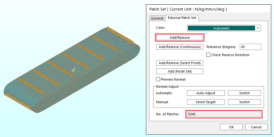
In the Database Window, confirm that SetPatch2 appears.
Click Exit to exit the Edit Mode.
It creates walls in the belt, container, and frame that the particles come in contact with.
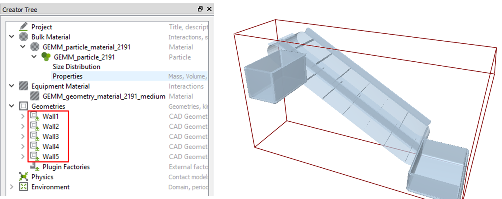
10.3.4.3.2. To create walls:
In the EDEM group of the External SPI tab, click the Walls function.
- Click Shell_CleatedBelt.SetPatch2 on the working window.Wall1 is created.
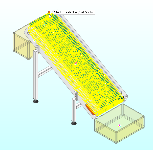
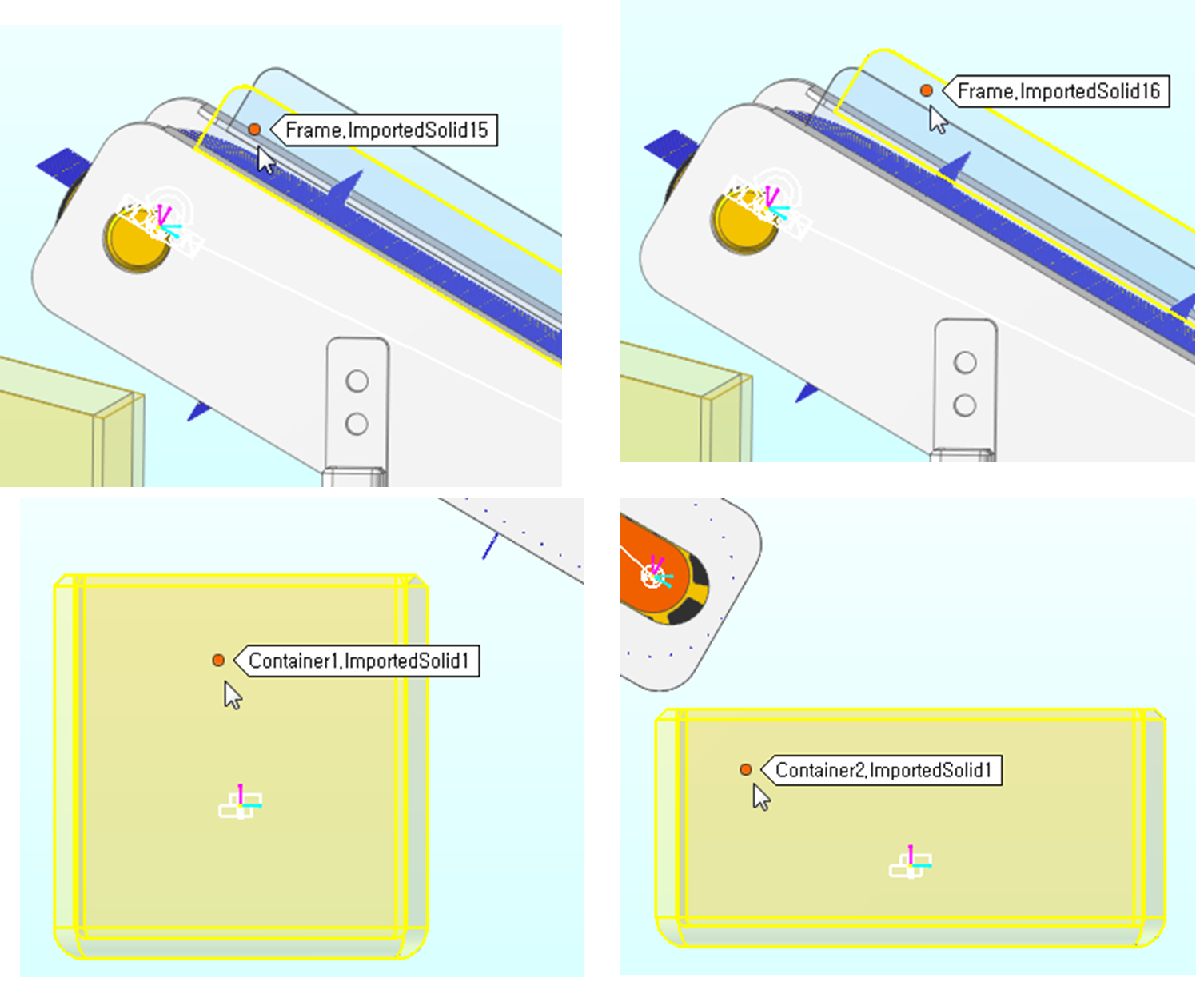
Repeat steps 1-2 to create walls using geometries.
Frame.ImportedSolid15
Frame.ImportedSolid16
Container1.ImportedSolid1
Container2.ImportedSolid1
10.3.4.4. To export a *.wall file:
In the EDEM group of the External SPI tab, click the Export function.
- When the Export dialog box appears, locate the folder you want to save the file to and click OK to save it.In the saved folder, the EDEM.wall file and Wall1.obj, Wall2.stl, Wall3.stl, Wall4.stl, and Wall5.stl are created.
Note
The CAD information of the wall geometry is stored in the files *.obj and *.stl. And the EDEM.wall file contains information about the position and orientation of wall geometries (*.obj, *.stl).
Geometry files always take information in the unit of Meter regardless of the system of units of RecurDyn.
Tip
Performing standalone analysis with RecurDyn
10.3.5. Creating an EDEM Model
EDEM can generate particles in many ways. Among them, we will try to generate particles on the belt using the method of generating particles at a constant speed.
10.3.5.1. Task Objectives
In this chapter, you will learn how to set particle properties and how to create particles using the material models provided by EDEM.
10.3.5.2. Estimated Time to Complete This Task
10 minutes
10.3.5.3. EDEM Creator
10.3.5.3.1. To execute EDEM and set RecurDyn coupling:
Execute EDEM.exe.
After executing EDEM, select Tool > Options.
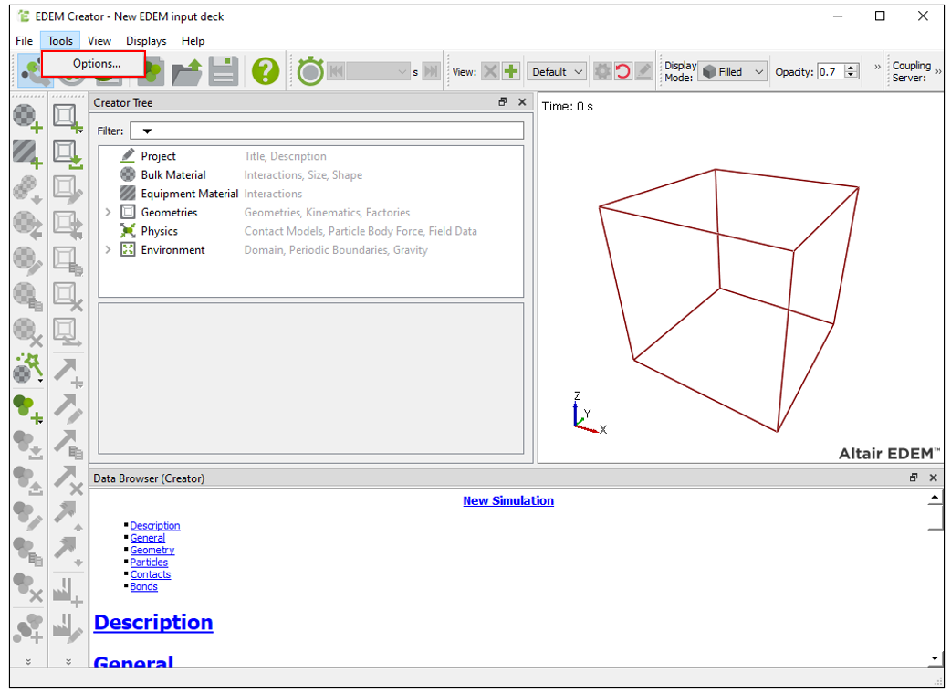
Change the unit settings to match the values entered when simulating the EDEM model later.
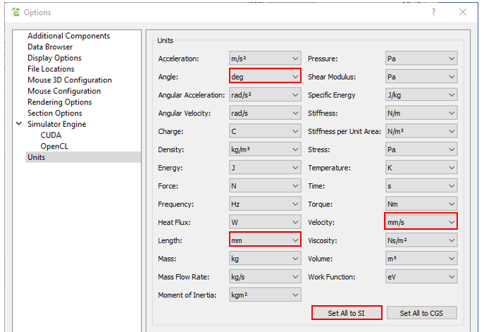
When the Options dialog window opens, click the Set All to SI button on the Units tab to reset the system of units.
Change the units of angle, length, and velocity as follows.
Angle: deg
Length: mm
Velocity: mm/s
Turn on the RecurDyn Coupling option in the Coupling Options group of the Additional Components tab.
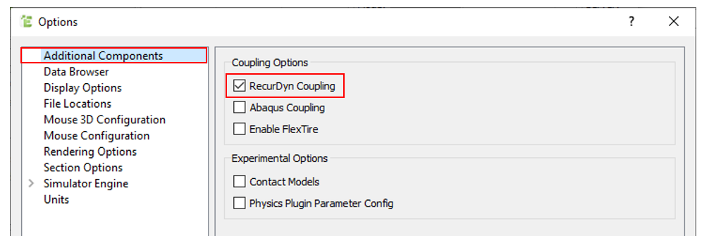
If you do not enable this option, you will not be able to import *.wall files exported from RecurDyn later.
Click OK.
From the GEMM database provided by EDEM, find and import an appropriate input deck corresponding to the particle properties.
Tip
GEMM (Generic EDEM Material Model) Database
The GEMM database contains thousands of material models representing a wide range of materials including rocks, soil, ore, etc. Users can download input decks for EDEM simulation from the vast amount of material information in the GEMM database.
10.3.5.3.2. To create material:
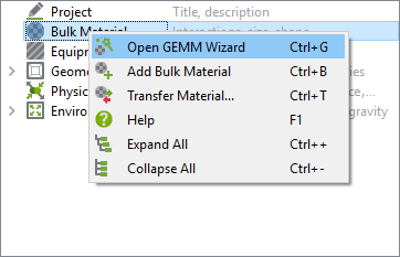
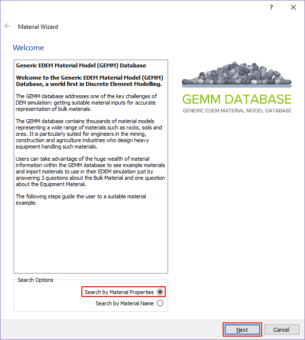
In the Database panel, right-click Bulk Material and click Open GEMM Wizard.
A Material Wizard dialog window appears.
After selecting Search by Material Properties, click Next.
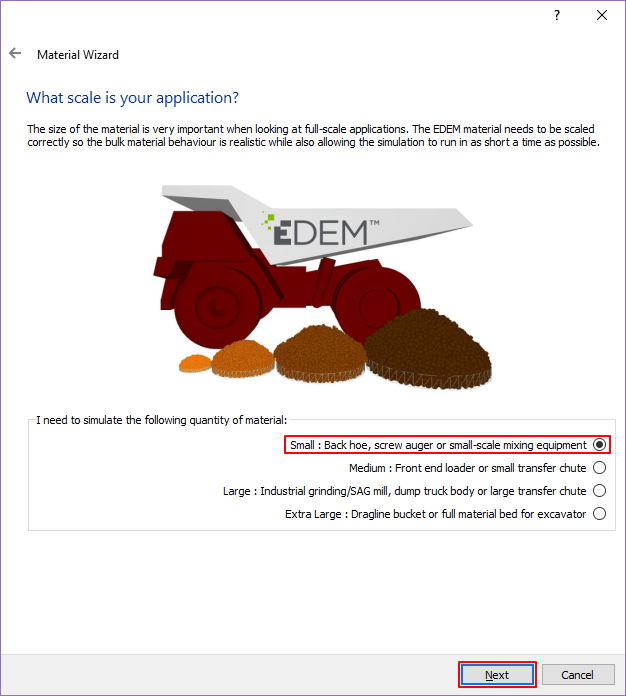
After selecting Small: Back hoe, Screw auger or small-scale mixing equipment, click Next.
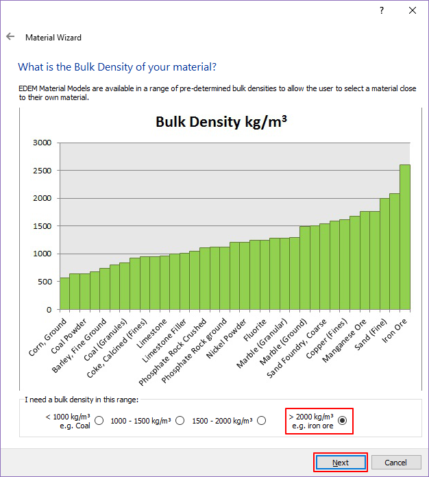
After selecting >2000kg/m^3, click Next.
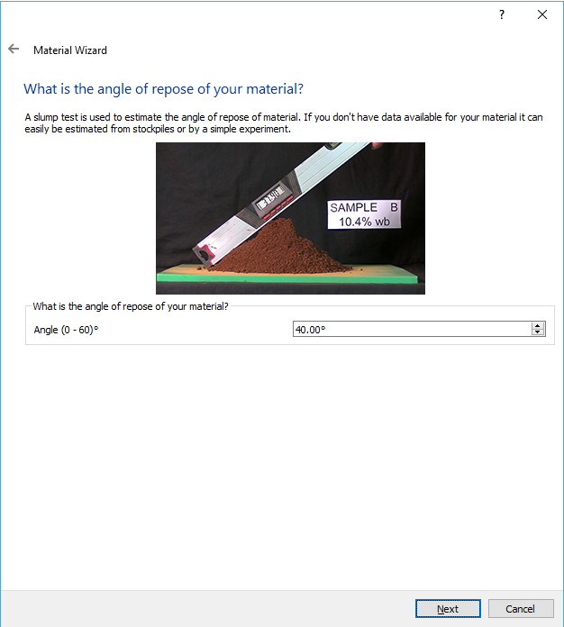
Enter 40 for Angle and click Next.
Select the material displayed on the first row and click Next.
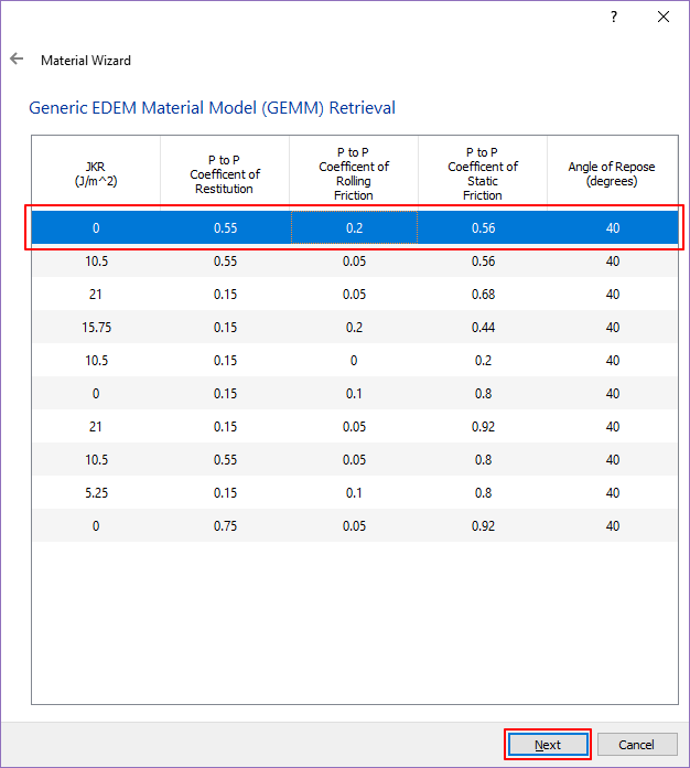
After selecting Medium Wall Friction, click Finish.
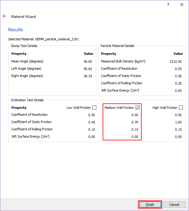
Bulk Material is the property value applied to the particles and Equipment Material is the property value applied to the wall. Materials with the input values matching the properties selected above are added respectively.
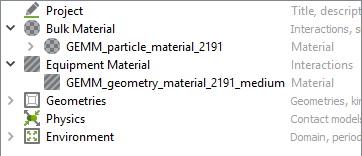
You can see that GEMM_particle_material_2191 and GEMM_geopetry_material_2191_medium are added to Bulk Material and Equipment Material in the Database panel as shown in the figure on the below.
The child of GEMM_particle_material_2191 contains the particle information GEMM_particle_2191. Try changing the size of the particle by modifying the property value.
10.3.5.3.3. To modify the particle shape:
Click Bulk Material > GEMM_particle_material_2191 > GEMM_particle_2191.
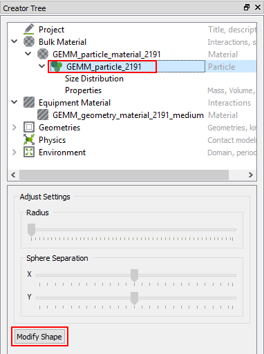
Click Modify Shape.
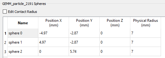
After clicking Triple Sphere, increase the Physical Radius to up to 7mm.
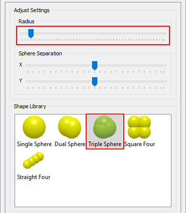
Make sure that sphere0, sphere1, and sphere2 are all 7mm as shown in the figure below. If the values are different, modify them as shown below.
This finishes the process for setting particles. Now, you have to import the wall exported from RecurDyn to EDEM.
10.3.5.3.4. To open the RecurDyn wall:
In the Database panel, right-click Geometries and click Import Geometry from RecurDyn.
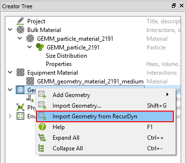
Open the EDEM.wall file exported from RecurDyn.
When the Import Options dialog window appears, set Choose Units to Meters and click OK.
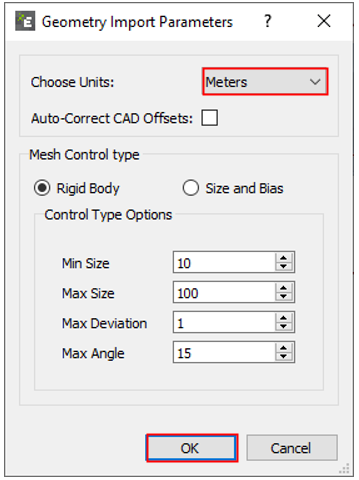
(As mentioned above, geometry files of the walls exported from RecurDyn are written in the unit of Meter.)
When the Geometry Import Parameters dialog window appears, click OK.
You can see that 5 walls are imported to the Database panel as shown below.
10.3.5.3.5. To define the zones created by particles:
In the Database panel, right-click Geometries and click Add Geometry > Polygon.
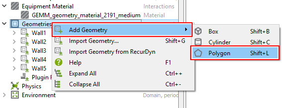
Under Geometries, New Section 5 is created.
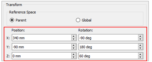
Under New Section 5, click Transform to change its position.
Position
X: 340mm
Y: -90mm
Z: 0mm
Rotation
X: 90deg
Y: 0deg
Z: 120deg
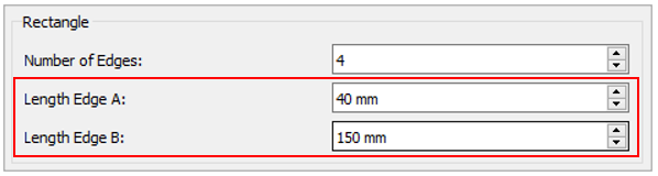
Under New Section 5, click Polygon to changes its shape.
Rectangle
Edge A: 40mm
Edge B: 150mm
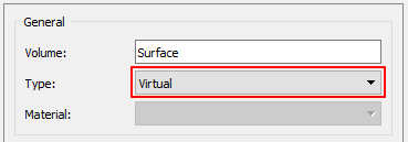
As shown in the figure on the below, New Section 5 is defined under the belt.
After clicking New Section 5, change the type as Virtual.
Type must be changed to Virtual to create a factory. (A factory is an entity that defines particle generation.)
In the Database panel, right-click New Section 5 and click Add Factory.
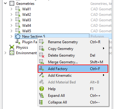
Under New Section 5, New Factory 1 is created.
Click New Factory 1 to modify as follows:
Particle Generation
Unlimited Number
Target Number (per second): 50
With these settings, 50 particles are generated per second at the Polygon location.
Parameters
Velocity: Fixed
It has a constant initial velocity when particles are generated. Try to modify the initial velocity of the particles.
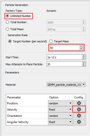
Click Config next to Velocity under Parameter.
In the Velocity Fixed dialog window, modify X to -300mm/s.
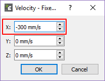
Click OK.
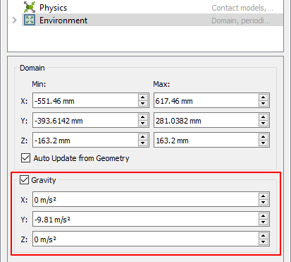
The Gravity of EDEM should be aligned in the same direction as RecurDyn.
10.3.5.3.6. To set gravity:
In the Database panel, click Environment.
Modify Gravity as follows.
X: 0 \(\mathbf{m/}\mathbf{s}^{\mathbf{2}}\)
Y: -9.81 \(\mathbf{m/}\mathbf{s}^{\mathbf{2}}\)
Z: 0 \(\mathbf{m/}\mathbf{s}^{\mathbf{2}}\)
10.3.5.3.7. To save the model:
This completes all the settings related to particle generation in EDEM Creator. Save the EDEM model.
10.3.5.4. EDEM Simulator
Now, set the elements related to the analysis.
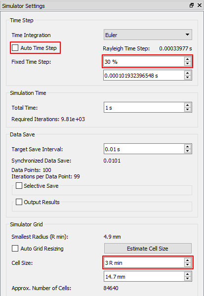
10.3.5.4.1. To set the simulator:
Click the Simulator icon in the ribbon menu.
Turn off the Auto Time Step option in the Time Step pane.
Set the Fixed Time Step option to 30%.
Set the Cell Size option to 3R in the Simulator Grid pane.
10.3.5.4.2. To activate coupling:
Click the Coupling Server icon at the top right of the ribbon to activate it.
When activated, it changes as shown below.

You are now ready for co-simulation. EDEM must be turned on for co-simulation with RecurDyn. Proceed to the next chapter with the program turned on.
10.3.6. Co-simulation
In this chapter, we will perform co-simulation using RecurDyn and EDEM to analyze the dynamic model and the behavior between particles.
10.3.6.1. Task Objectives
In this chapter, you will learn how to perform co-simulation in RecurDyn.
10.3.6.2. Estimated Time to Complete This Task
150 minutes
10.3.6.3. Co-simulation
10.3.6.3.1. To perform co-simulation in RecurDyn:
Run RecurDyn and open the model you saved in Chapter 4.
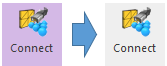
In the EDEM group of the External SPI tab, activate the Connect function.
In the Simulation Type group of the Analysis tab, click the Dynamic/Kinematic Analysis function.
On the General page, modify as follows.
End Time: 10
Step: 1000
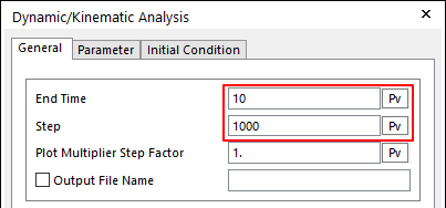
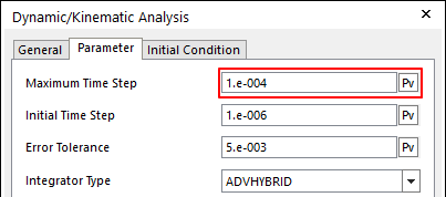
On the Parameter page, set Maximum Time Step as 1.e-004.
Click Simulate.
RecurDyn and EDEM perform the co-simulation.
10.3.6.3.2. To view the result:
On the Analysis tab, in the Animation Control group, click the Play function to view the animation.
10.3.6.4. EDEM Analyst
Try to replay the result analyzed by EDEM.
10.3.6.4.1. To set the simulator:
Click the Analyst icon in the EDEM ribbon menu.
Click the Jump to start icon to move to 0 frame.
- Click Animate forwards to replay the animation.You can see the same animation as in RecurDyn.
10.3.7. Analyzing and Reviewing the Results
In this chapter, we will analyze the results from Chapter 6 using the Post Tool of RecurDyn.
10.3.7.1. Task Objectives
In this chapter, you will learn how to use the SPI Post Tool in RecurDyn.
10.3.7.2. Estimated Time to Complete This Task
10 minutes
10.3.7.3. Post Process
Analyze the results using the Particle Post function provided by RecurDyn.
10.3.7.3.1. To create particle sensors:
- In the Post-Process group of the External SPI tab, click the Sensors function.The Particle Sensor dialog window appears.
Click Add Box.
Enter the following information.
EDEM_1
Ground
-540, 330, -160
606, -387, 160
P_Sensor1 is created.
Modify the color of P_Sensor1 to Blue.
Again, click Add Box.
Enter the following information.
EDEM_1
Container1
-530, 110, -150
-370, -60, 150
P_Sensor2 is created.
Modify the color of P_Sensor2 to Red.
Again, click Add Box.
Enter the following information.
EDEM_1
Container2
366, -270, -150
596, -377, 150
P_Sensor3 is created.
Modify the color of P_Sensor3 to Green.
Click Update.
Click View of P_Sensor1 and P_Sensor2 to display the Scope.
Click OK.
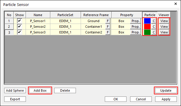
Three box-shaped sensors are created in the same position as shown in the figure. If you replay animation, the sensors will be highlighted when a particle enters the box.
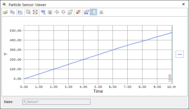
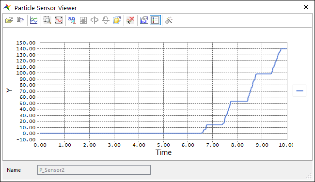
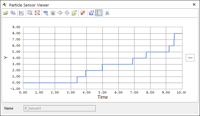
Analyze the Scope results of the Viewer.
First, the result of P_Sensor1 is the number of particles in the entire space, which shows the rate of particle generation and inflow. You can see that the value is about 50/sec. and matches the generation rate entered in EDEM.
The result of the second P_Sensor2 is the number of particles being carried by the belt and entering Container1.
The result of the last P_Sensor3 is the number of particles entering Container2 instead of being carried by the belt.
For reference, in EDEM, particles are set to have a random position and orientation when they are created. Therefore, the results can be slightly different from the results shown above.