11.1. 4WD Loader Tutorial (eTemplate)
11.1.1. Precautions
In this tutorial, Header Type and Parameter Definition are distinguished by color when inputting Excel data in the sheet, and colors have no effect on the data.
When using eTemplate in this tutorial, open a New Model to start the next eTemplate before opening an eTemplate.
This tutorial is designed so that users can copy and use Excel data every chapter. Copy the area with the left sign onto the sheet.
11.1.1.1. Prerequisites
Before starting this tutorial, follow the ProcessNet 4WD Loader Tutorial of RecurDyn Tutorial first.
11.1.1.2. Overview
In this tutorial, you will learn how to:
Create a set of contacts automatically using eTemplate.
Make the modeling process more effective and accurate using eTemplate.
Use S4PARK Technology based on Excel, not on the coding.
11.1.1.3. Task Objective
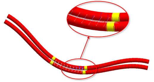
In this tutorial, you will learn how to simulate a pair of hoses in the 4WD Loader. The hoses are linked to the hydraulic pump at the rear of the vehicle to the cylinder of the frontal Loader linkage, and the Loader is steers by articulation. The hoses bend as the two sections of the frame articulate and may contact each other.
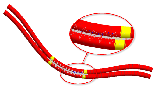
It is important to understand contacts to predict any binding or wear problem. In addition, as it is hard to estimate actual motions of the hoses and the location of contacts, any contact between the segments of the two hoses as shown in the figure below needs to be defined to figure out where the contact happens and how much contact force applies in the simulation. This may become boring and cause many errors due to a number of repeated operations. Using eTemplate, however, can make the modeling process more effective and accurate. Whereas ProcessNet requires such a complicated process of coding, you can use eTemplate by inputting simple basic data in Excel.
11.1.2. Opening the 4WD Hydraulic Hose Model
In this section, you will learn how to import and setup a model to use eTemplate.
11.1.2.1. Estimated Time to Complete
10 minutes
11.1.2.2. Starting RecurDyn
11.1.2.2.1. To start RecurDyn and open recent models:
On the Desktop, double-click the RecurDyn icon.
Close the Start RecurDyn dialog box, as Recent Models, not a New Model, need to be used.
From the File menu, click Open.
From the eTempalte tutorial directory (<InstallDir>\Help\Tutorial\eTemplate\Tut1_4WD_Loader), select the 4WD_Loader_Start.rdyn file.
Click Open.
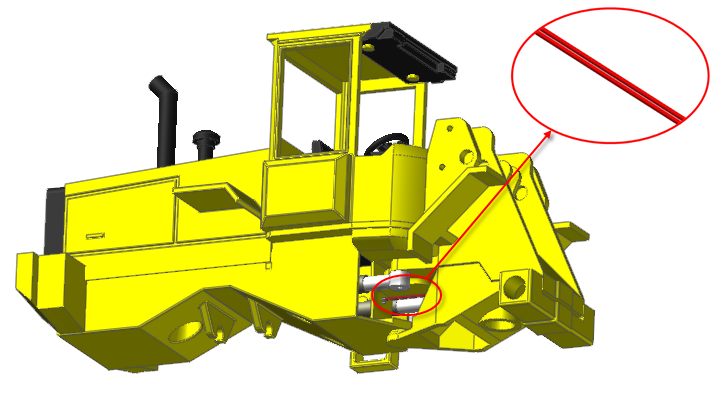
Then you will see the following model..
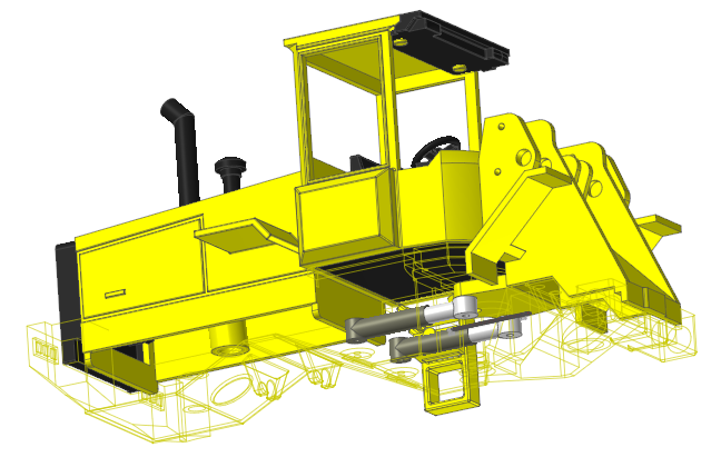
The red line means the hydraulic hose to learn about in this tutorial.
Tip
The hoses appear as above by selecting the View mode (Render Each Object) as they look dim at the bottom of the vehicle. (If it is hard to see the hoses, check if the current mode is the Shaded view mode is and change the mode to Render Each Object view mode.)
11.1.2.2.2. To save the initial model:
From the File menu, click Save As.
Save the model different directory, because you cannot simulation in tutorial directory.
11.1.2.2.3. To Change the Model Layer Number:
Change Layer Number of bodies except for the hydraulic hoses so that the hydraulic hoses can be seen easily.
Activate the Bodies group of Database Window.
Click CabMain Body and click Steer_Cyl_OD_L Body with the Shift key.
Right-click and select Properties.
From the General page, change Layer Number to 2.
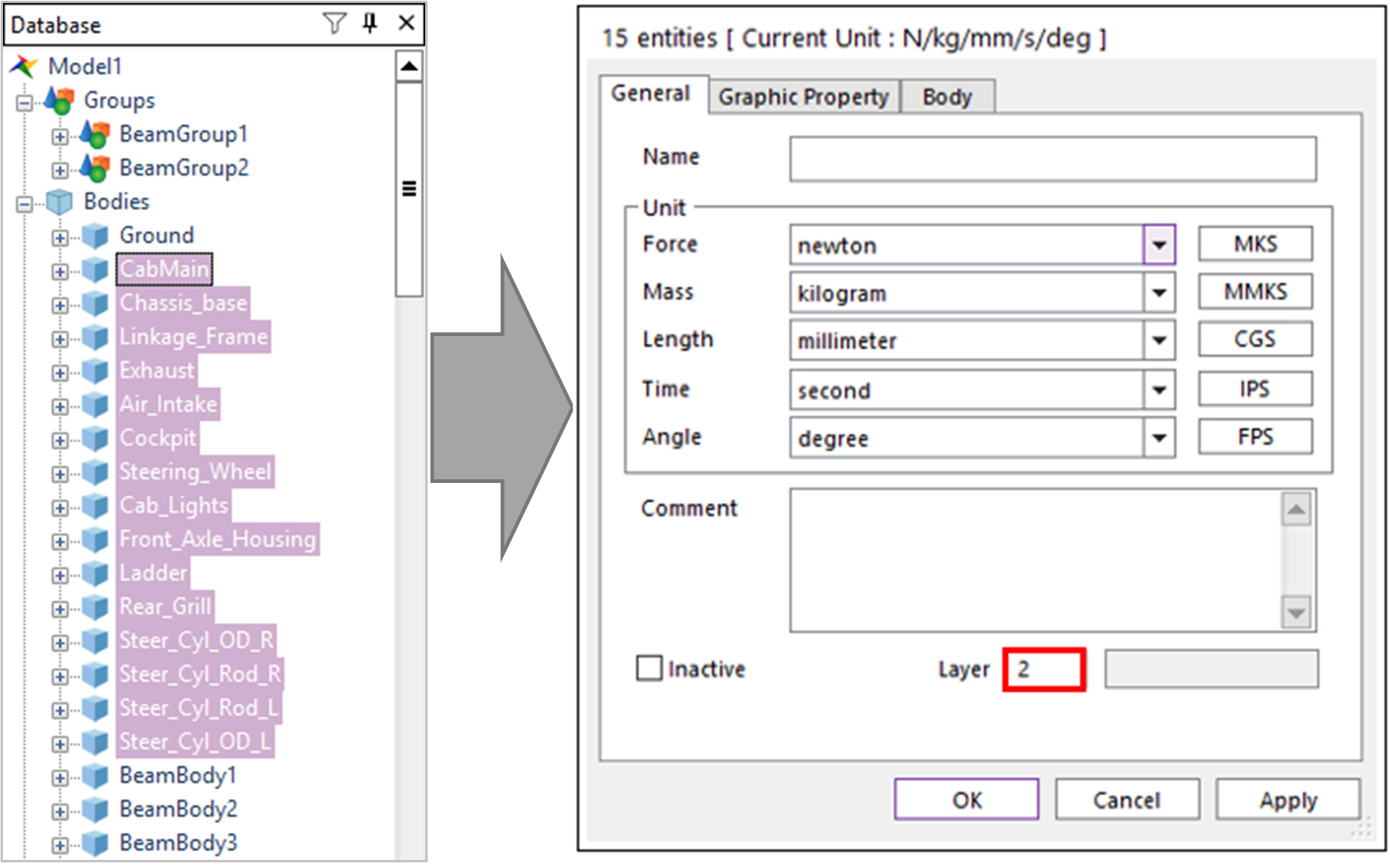
Click OK.
- Click the Layer Settings tool in Render Toolbar.Layer Settings Dialog appear. Check the Show User-Defined Layer to filter the defined layers.
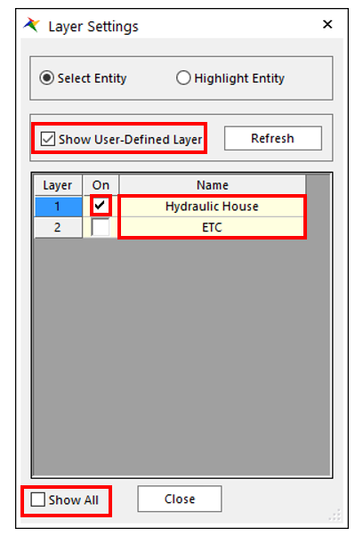
Check 1st Layer only and set the brief names.
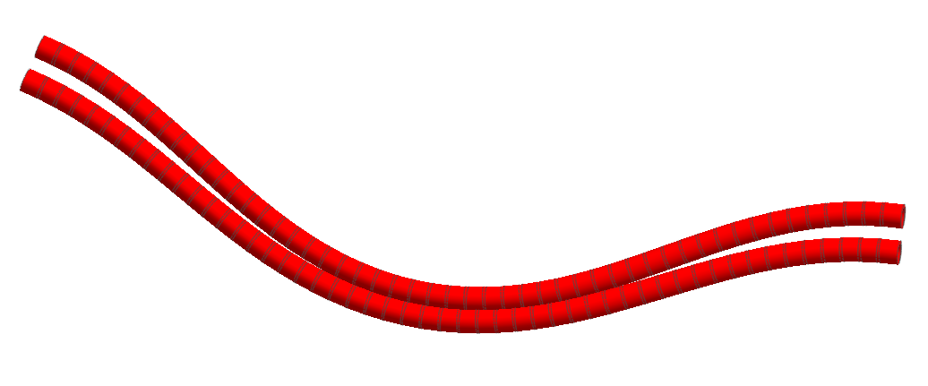
Close Layer Settings dialog. Only the hydraulic hoses appear on the working window.
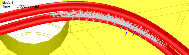
From the Simulation Type group in the Analysis tab, click the Dynamic / Kinematic Analysis function and perform an analysis.
- Check the result.The hydraulic hoses change as shown below. In the below figure, the hydraulic hoses contact with each other in the center.So, in Chapter 3, you will learn how to make the hydraulic hoses contact with each other using Solid Contact.
11.1.3. Defining the Auto Contact
11.1.3.1. Task Objective
You will learn how to create eTemplate that creates contact between segments of the hydraulic hoses.
Collect information to create the RecurDyn entity.
Use Solid Contact in RecurDyn.
Modify the Solid Contact parameters.
After performing a simulation, you will learn how to re-create contact for better results.
11.1.3.2. Estimated Time to Complete
35 minutes
11.1.3.3. Understanding the Contacts to be Created
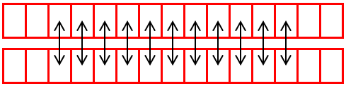
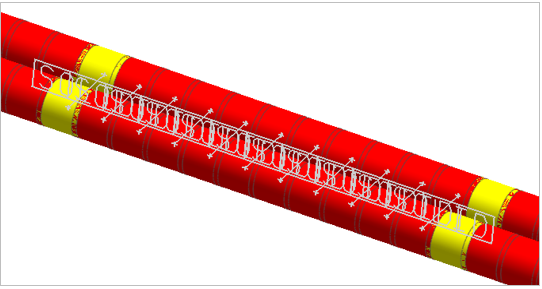
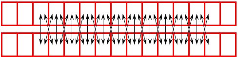
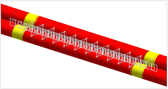
In Chapter 1, we have explained two hoses with 50 segments as shown in the following figure. Loader and Frame of hoses are connected at both ends, and the central rotation axis of Loader applies between both ends. When articulation occurs one hose tends to be stretched more and the other hose stretched less. Since contacts happen in the center of the hoses due to their different curves, create contact in the center.

With eTemplate, 11 contacts will be created in the center of the hoses as shown below. Whereas ProcessNet requires a complicated process of coding, you can use eTemplate by inputting simple basic data in Excel.
11.1.3.4. Creating the Solid Contact
11.1.3.4.1. To collect information to create the RecurDyn entity:
Examine the hydraulic hose body to add Solid Contact.
The hydraulic hoses consist of BeamGroup1 and BeamGroup2.
BeamGroup1 has 51 bodies from BeamBody1 to BeamBody51.
BeamGroup2 has 51 bodies from BeamBody52 to BeamBody102.
Think about how BeamGroup1 and BeamGroup2 contact with each other.
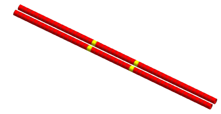
BeamGroup1 uses from BeamBody20 to BeamBody31, and BeamGroup2 uses from BeamBody71 to BeamBody82.
Change colors to make it easier to find each BeamBody in the BeamGroup.
From the Database, left click BeamBody to select all.
Click the Working window and right-click BeamBody20 to select BeamBody20 only, and a window to select Property will appear.
Select Property, move to the Graphic Property page, and change the color to yellow.
Repeat steps 8 through 10 for BeamBody31, BeamBody71, and BeamBody82.
From the Contact group in the Professional tab, click the Solid Contact function.
Make sure that Solid, Solid Creation Method Option is selected and click both BeamBody20 and BeamBody71.
Check the created Solid Contact Property.
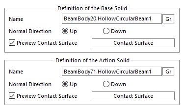
Check that Base Geometry is BeamBody20.HollowCircularBeam1 and Action Geometry is BeamBody71.HollowCircularBeam1.
When completing eTemplate, input the name of the body and geometry in the definition of the contact.
Before creating eTemplate, delete SolidContact1 created above.
11.1.3.5. Defining the Template Sheet
11.1.3.5.1. To define the Template_Format Sheet:
Define the template to be used in Modification Mode.
- Open Excel and then create a sheet called Template_Format.Template_Format Sheet is a sheet that defines how to process the template data.
In the Template_Format sheet, enter the header and parameter information that defines the template format.
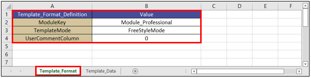
Template_Format_Definition
Value
ModuleKey
Module_professional
TemplateMode
FreeStyleMode
UsercommentColumn
0
ModuleKey: Select a RecurDyn product module.
TemplateMode: Select a parameter arrangement method.
UserCommentColumn: Enter a value between 1 and 5 to use one of the columns between A and E in the sheet. If you don’t want to use a column, enter 0.
Tip
Copying the header and parameters using the eTemplate Helper
On the Customize tab, in the eTemplate group, click the Helper function to run the eTemplate Helper.
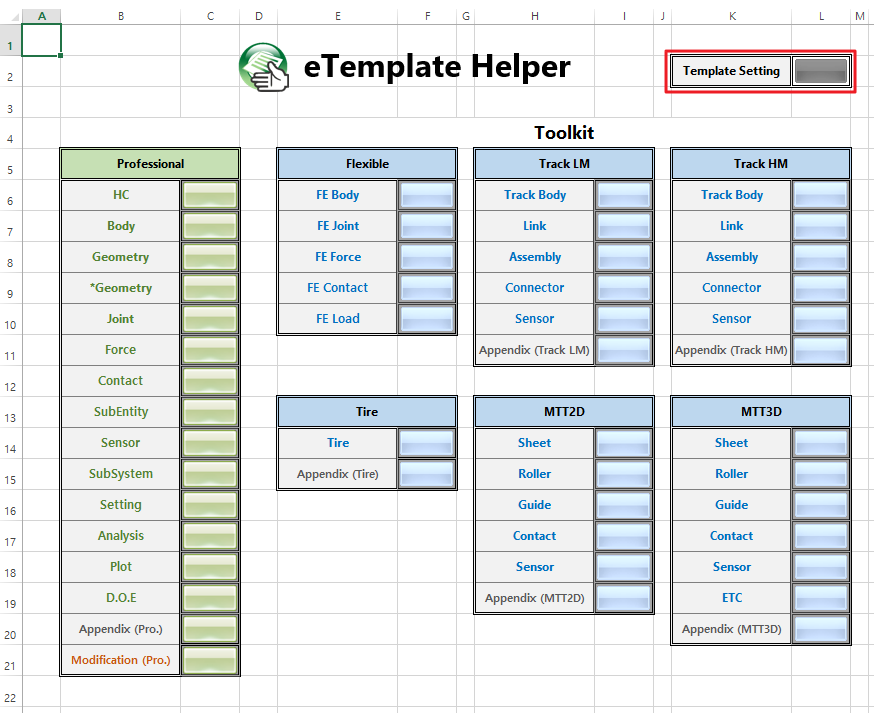
Click the Template Setting button.
Copy the header and parameters of the Template_Format sheet to the template.
- Edit the values so that they fit the tutorial.You may also need to add additional headers and parameters as you continue with this tutorial.Or, you can copy the headers and parameters from the completed template file provided by RecurDyn.(Template Fil path: <InstallDir>\Help\Tutorial\eTemplate\Tut1_4WD_Loader\4WD_Loader_Template.xlsx)
11.1.3.5.2. To define the Template_Data Sheet:
You must configure the Template_Data sheet in order to enter the values used in Creation Mode.
Create a sheet called Template_Data.
In the Template_Data sheet, enter the headers and parameters in order to create the Solid Contact.

For the Solid Contact, enter the following values:
Header_Contact_Solid
Name
BaseGeometry
ActionGeometry
Contact_Solid
Name: Name of solid contact.
BaseGeometry: Name of the base geometry of solid contact
ActionGeometry: Name of the action geometry of solid contact
Enter the name one by one from SolidContact1 to SolidContact11.
Based on the information collected earlier, input from BeamBody20.HollowCircularBeam1 to BeamBody30.HollowCircularBeam1 as the body of BeamGroup1 in Base Geometry. Note that HollowCircularBeam, geometry contained in each body needs to be entered as well.
Based on the information collected earlier, input from BeamBody71.HollowCircularBeam1 to BeamBody81.HollowCircularBeam1 as the body of BeamGroup2 in Action Geometry.
Header_Contact_Solid
Name
BaseGeometry
ActionGeometry
Contact_Solid
SolidContact1
BeamBody20.HollowCircularBeam1
BeamBody71.HollowCircularBeam1
Contact_Solid
SolidContact2
BeamBody21.HollowCircularBeam1
BeamBody72.HollowCircularBeam1
Contact_Solid
SolidContact3
BeamBody22.HollowCircularBeam1
BeamBody73.HollowCircularBeam1
Contact_Solid
SolidContact4
BeamBody23.HollowCircularBeam1
BeamBody74.HollowCircularBeam1
Contact_Solid
SolidContact5
BeamBody24.HollowCircularBeam1
BeamBody75.HollowCircularBeam1
Contact_Solid
SolidContact6
BeamBody25.HollowCircularBeam1
BeamBody76.HollowCircularBeam1
Contact_Solid
SolidContact7
BeamBody26.HollowCircularBeam1
BeamBody77.HollowCircularBeam1
Contact_Solid
SolidContact8
BeamBody27.HollowCircularBeam1
BeamBody78.HollowCircularBeam1
Contact_Solid
SolidContact9
BeamBody28.HollowCircularBeam1
BeamBody79.HollowCircularBeam1
Contact_Solid
SolidContact10
BeamBody29.HollowCircularBeam1
BeamBody80.HollowCircularBeam1
Contact_Solid
SolidContact11
BeamBody30.HollowCircularBeam1
BeamBody81.HollowCircularBeam1
If the Solid Contact is created as above, parameters are created as default values of RecurDyn. However, basic stiffness and damping values for the Solid Contact are too high. So, in order to lower the values, create an option to set two Contact Parameters.
To the Contact of eTemplate, add the ContactProperty option to change stiffness and damping among other characteristic values.
First of all, to define values to be input in ContactProperty, set stiffness and damping in the name of ContactProperty_Info.
Header_Info_ContactProperty
Name
DampingCoefficient
StiffnessCoefficient
Info_ContactProperty
ContactProperty_Info
0.1
1000
Input ContactProperty_Info as defined above in the ContactProperty option of Solid Contact onto the right of ActionGeometry.
After performing a simulation, add the option to view Force Display as well.
ContactProperty
ForceDisplay
ContactProperty_Info
Action
ContactProperty_Info
Action
ContactProperty_Info
Action
ContactProperty_Info
Action
ContactProperty_Info
Action
ContactProperty_Info
Action
ContactProperty_Info
Action
ContactProperty_Info
Action
ContactProperty_Info
Action
ContactProperty_Info
Action
ContactProperty_Info
Action
eTemplate appears as shown in the figure below.
Save the created eTemplate.
11.1.3.5.3. To run the eTemplate:
From eTemplate group in the Customize tab, click the Run function.
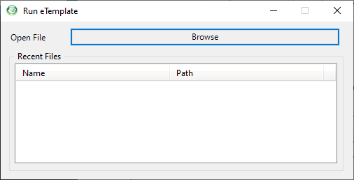
- Click Browse and Import the created eTemplate file.A contact model is created as below.
11.1.3.6. Performing a Simulation
11.1.3.6.1. To perform a simulation:
From the Simulation Type group in the Analysis tab, click the Dynamic / Kinematic Analysis function.
To perform a simulation, set End Time to 2.0, Step to 300, and Plot Multiplier Step Factor to 5, respectively.
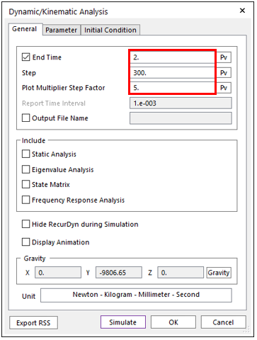
Click Simulate. The simulation may last 5 - 10 minutes, depending on the speed of the computer.
11.1.3.7. Viewing the Result
11.1.3.7.1. To view the result:
From the Animation Control group in the Analysis tab, click the Play function.
At the end of the simulation, the hoses appear as in the figure below.
At the end of the simulation, Force seems like a bit irregular. Observing their motions shows that they are slipping away from each other.
This is because of failed contact between relevant segments, and to solve this problem, setting the contact between the neighboring Segments is necessary.
The next chapter shows how to set the contact at adjacent segments.
11.1.4. Defining Segment Contact
11.1.4.1. Task Objective
Failed contact between segments can cause a trouble, and to solve this problem, setting the contact between the neighboring segments is necessary.
Modify the eTemplate data.
Set Segment Contact using Solid Contact.
After performing a simulation, you will see better results.
11.1.4.2. Estimated Time to Complete
15 minutes
11.1.4.3. Defining Segment Contact
Failed contact between segments can cause a trouble, and to solve this problem, setting the contact between the neighboring segments is necessary. This phenomenon appears as in the following figure.
11.1.4.3.1. To delete the eTemplate Solid Contact:
Before creating an additional Solid Contact, delete the contact created in Chapter 3.
When importing eTemplate, it is impossible to create if there is an entity with the same name.
From the Database Window, select the first solid contact, SolidContact1.
Pressing the Shift key, select the last solid contact, SolidContact11.
Press the Delete key.
11.1.4.3.2. To create additional eTemplate Solid Contact:
Open eTemplate created in Chapter 3 and create two types of additional Contact Groups.
First of all, set the name of the contact created between the i+1 th segment of Hydraulic Hose 1 and the j th segment of Hydraulic Hose 2 by adding “a.”
From the information collected earlier, input from BeamBody21.HollowCircularBeam1 to BeamBody31.HollowCircularBeam1 as the body of BeamGroup1 in the Base Geometry.
From the information collected earlier, input from BeamBody71.HollowCircularBeam1 to BeamBody81.HollowCircularBeam1 as the body of BeamGroup2 in the Action Geometry.
Using the definition of eTemplate of Solid Contact, input as below.
Header_Contact_Solid
Name
BaseGeometry
ActionGeometry
ContactProperty
ForceDisplay
Contact_Solid
SolidContact1a
BeamBody21.HollowCircularBeam1
BeamBody71.HollowCircularBeam1
ContactProperty_Info
Action
Contact_Solid
SolidContact2a
BeamBody22.HollowCircularBeam1
BeamBody72.HollowCircularBeam1
ContactProperty_Info
Action
Contact_Solid
SolidContact3a
BeamBody23.HollowCircularBeam1
BeamBody73.HollowCircularBeam1
ContactProperty_Info
Action
Contact_Solid
SolidContact4a
BeamBody24.HollowCircularBeam1
BeamBody74.HollowCircularBeam1
ContactProperty_Info
Action
Contact_Solid
SolidContact5a
BeamBody25.HollowCircularBeam1
BeamBody75.HollowCircularBeam1
ContactProperty_Info
Action
Contact_Solid
SolidContact6a
BeamBody26.HollowCircularBeam1
BeamBody76.HollowCircularBeam1
ContactProperty_Info
Action
Contact_Solid
SolidContact7a
BeamBody27.HollowCircularBeam1
BeamBody77.HollowCircularBeam1
ContactProperty_Info
Action
Contact_Solid
SolidContact8a
BeamBody28.HollowCircularBeam1
BeamBody78.HollowCircularBeam1
ContactProperty_Info
Action
Contact_Solid
SolidContact9a
BeamBody29.HollowCircularBeam1
BeamBody79.HollowCircularBeam1
ContactProperty_Info
Action
Contact_Solid
SolidContact10a
BeamBody30.HollowCircularBeam1
BeamBody80.HollowCircularBeam1
ContactProperty_Info
Action
Contact_Solid
SolidContact11a
BeamBody31.HollowCircularBeam1
BeamBody81.HollowCircularBeam1
ContactProperty_Info
Action
Secondly, set the name of the contact created between the ith segment of Hydraulic Hose 1 and the j+1th segment of Hydraulic Hose 2 by adding “b”
From the information collected earlier, input from BeamBody20.HollowCircularBeam1 to BeamBody30.HollowCircularBeam1 as the body of BeamGroup1 in the Base Geometry.
From the information collected earlier, input from BeamBody72.HollowCircularBeam1 to BeamBody82.HollowCircularBeam1 as the body of BeamGroup2 in the Action Geometry.
Using the definition of eTemplate of Solid Contact, input as below.
Header_Contact_Solid
Name
BaseGeometry
ActionGeometry
ContactProperty
ForceDisplay
Contact_Solid
SolidContact1b
BeamBody20.HollowCircularBeam1
BeamBody72.HollowCircularBeam1
ContactProperty_Info
Action
Contact_Solid
SolidContact2b
BeamBody21.HollowCircularBeam1
BeamBody73.HollowCircularBeam1
ContactProperty_Info
Action
Contact_Solid
SolidContact3b
BeamBody22.HollowCircularBeam1
BeamBody74.HollowCircularBeam1
ContactProperty_Info
Action
Contact_Solid
SolidContact4b
BeamBody23.HollowCircularBeam1
BeamBody75.HollowCircularBeam1
ContactProperty_Info
Action
Contact_Solid
SolidContact5b
BeamBody24.HollowCircularBeam1
BeamBody76.HollowCircularBeam1
ContactProperty_Info
Action
Contact_Solid
SolidContact6b
BeamBody25.HollowCircularBeam1
BeamBody77.HollowCircularBeam1
ContactProperty_Info
Action
Contact_Solid
SolidContact7b
BeamBody26.HollowCircularBeam1
BeamBody78.HollowCircularBeam1
ContactProperty_Info
Action
Contact_Solid
SolidContact8b
BeamBody27.HollowCircularBeam1
BeamBody79.HollowCircularBeam1
ContactProperty_Info
Action
Contact_Solid
SolidContact9b
BeamBody28.HollowCircularBeam1
BeamBody80.HollowCircularBeam1
ContactProperty_Info
Action
Contact_Solid
SolidContact10b
BeamBody29.HollowCircularBeam1
BeamBody81.HollowCircularBeam1
ContactProperty_Info
Action
Contact_Solid
SolidContact11b
BeamBody30.HollowCircularBeam1
BeamBody82.HollowCircularBeam1
ContactProperty_Info
Action
Input ContactProperty_Info as defined in Chapter 3 in the ContactProperty option of the Solid Contact on the right of ActionGeometry.
After performing a simulation, add the option to view Force Display as well at Force.
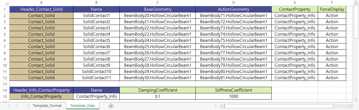
Upon completion of input, Template_Data Sheet appears as below.
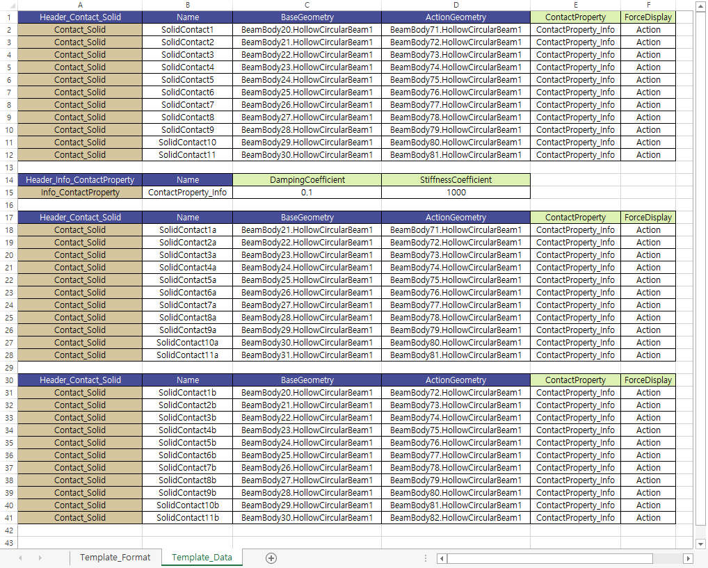
Save the created eTemplate.
11.1.4.3.3. To run the eTemplate:
From the eTemplate group into the Customize tab, click the Run function.
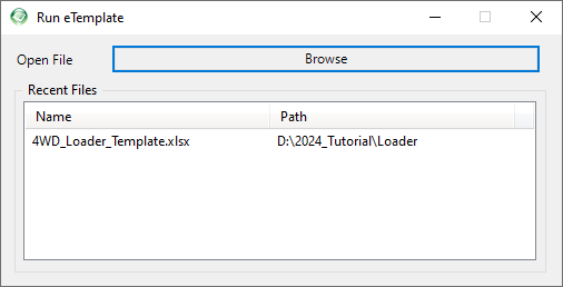
The eTemplate record made in Chapter 3 is saved in Recent Files.
- Double-click the record to import the eTemplate files automatically.The new contact models are created as shown in the figure below.
11.1.4.4. Performing a Simulation
11.1.4.4.1. To perform a simulation
From the Simulation Type group in the Analysis tab, click the Dynamic / Kinematic Analysis function.
Click Simulate.
11.1.4.5. Viewing the Result
11.1.4.5.1. To view the result:
From the Animation Control group in the Analysis tab, click the Play function.
At the end of the simulation, the hoses appear deformed as in the following figure.
Contact Force looks smoother.
Now, you will know how to create complicated contacts using eTemplate.