1.2. Engine with Propeller Tutorial (Professional)
1.2.1. Getting Started
1.2.1.1. Objective
In this tutorial, you will learn how to:
Import geometry that was created by using a CAD system
Organize the imported geometry into the bodies needed for the simulation
Define translational and rotational spring forces
Define scopes that display a model output within a floating window in the modeling environment
You will also practice skills that you learned in the previous tutorial, 3D Slider Crank:
Constraint modeling to connect the left and right blades with the propeller hub and to connect the propeller hub to the engine
Running a simulation, animating the model, and plotting the results
In all, you will:
Create a simple model of an aircraft engine with an attached propeller
Study the relationship between the motion of a point at the tip of the propeller and the motion of the drive shaft
Express model outputs in the form of plots and animations
1.2.1.2. Audience
This tutorial is intended for new users of RecurDyn. All new tasks are explained carefully.
1.2.1.3. Prerequisites
Users should firstly work through the 3D Slider Crank Tutorial or the equivalent. We assume that you have a basic knowledge of physics.
1.2.1.4. Procedures
The tutorial is comprised of the following procedures. The estimated time to complete each procedure is shown in the table
Procedures |
Time (minutes) |
Simulation environment set up and geometry import |
15 |
Organizing the geometry |
20 |
Joint/motion creation |
15 |
Force creation |
10 |
Analysis |
5 |
Scope and force display creation |
10 |
Design study |
15 |
Plotting/Animation |
10 |
Total |
100 |
1.2.1.5. Estimated Time to Complete
100 minutes
1.2.2. Creating the Initial Model
1.2.2.1. Task Objective
You will begin this tutorial by learning how to set up the simulation environment, including setting units, materials, gravity, and the working plane. In addition, you will learn how to import the CAD geometry that models the propeller blade, propeller hub, and engine housing.
1.2.2.2. Estimated Time to Complete
15 minutes
1.2.2.3. Starting RecurDyn
1.2.2.3.1. To start RecurDyn and create a new model:
On your Desktop, double-click the RecurDyn icon. RecurDyn starts up and the Start RecurDyn dialog box appears.
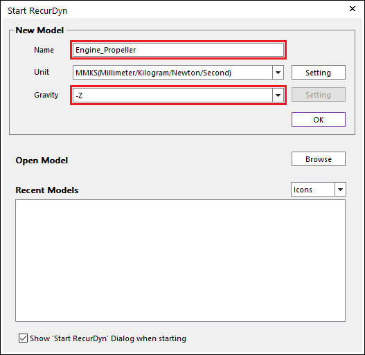
In the model Name text box, enter the name of the new model as Engine_Propeller.
Set Gravity to –Z and leave the defaults for all the other options.
Click OK.
Tip
Allowed Characters for Entities
You cannot use spaces or special characters in the model name or in any RecurDyn entity. You can use the underscore character to add spacing to improve the readability of the name.
1.2.2.4. Importing the CAD Geometry
Now you will import the CAD geometry for the propeller blade, propeller hub, and engine housing. This is a typical way you would use RecurDyn. Create the modeling geometry in a CAD program and import the CAD geometry into RecurDyn for analysis.
1.2.2.4.1. To import the propeller blade geometry:
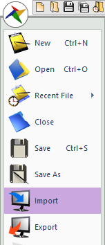
From the File menu, click the Import function.
In the Import window that appears, set Files of type to ParaSolid File (*.x_t,*.x_b …).
- In the EngineWithPropeller folder of the RecurDyn installation, select the file: Prop_Blade.X_T.(The file path: <InstallDir>\Help\Tutorial\Professional\EngineWithPropeller)
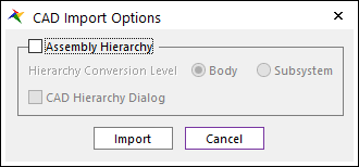
Click Open. The CAD Import Options window appears. Clear the Assembly Hierarchy checkbox and click the Import button.
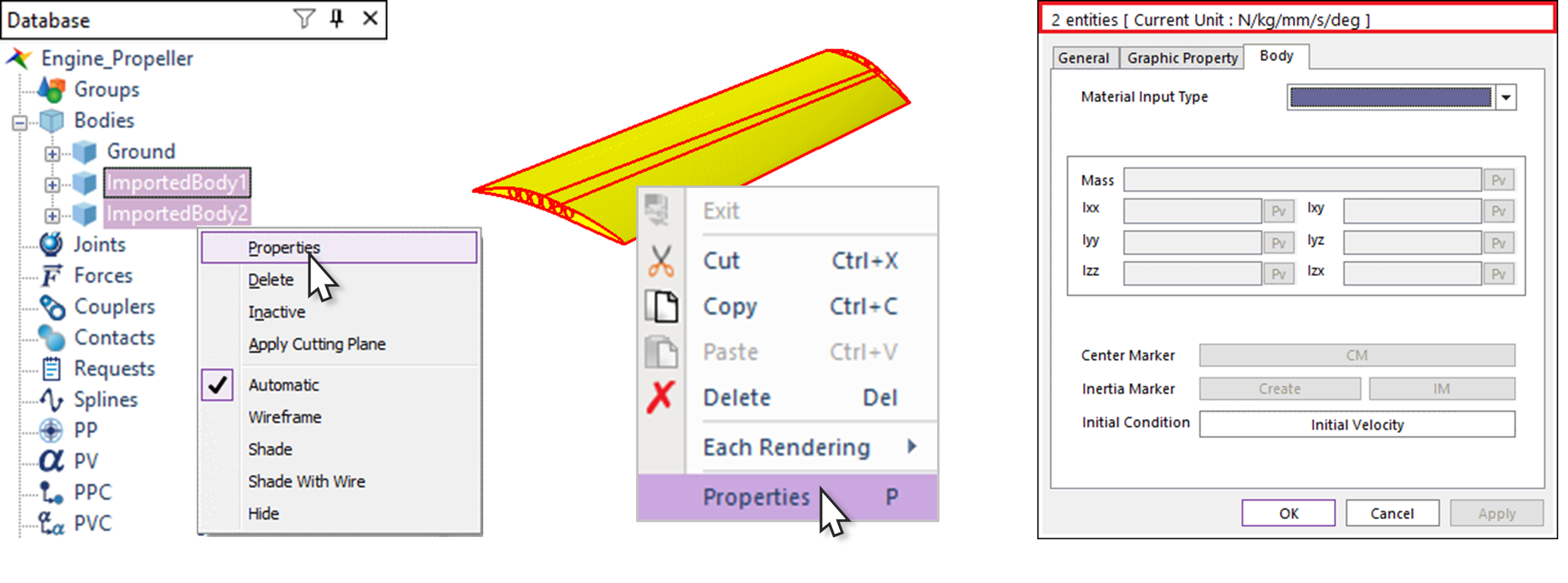
Notice that the blade geometry appears in the Working window and the body names ImportedBody1 and ImportedBody2 appear in the Database window.
Select both ImportedBody1 and ImportedBody2 and enter the Multi-Properties dialog of them.
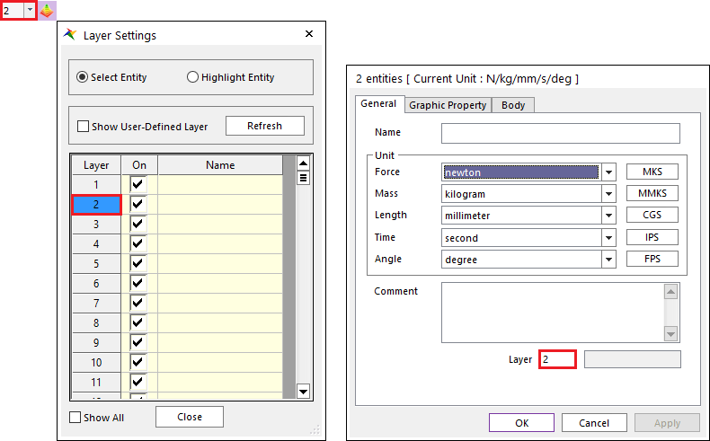
Set the Layer from 1 to 2 in the General page.
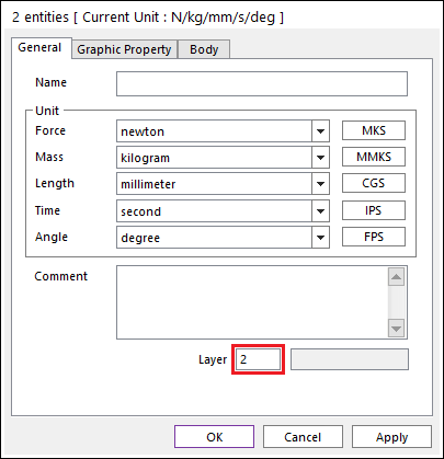
Click OK.
Tip
How to display the Properties dialog box for an entity
You can modify parameters of entities at the Properties dialog of selected ones.
Here are 3 methods below to open the Properties dialog.
Click Properties at the Pop-up menu after clicking right mouse button on a desired entity.
Click Properties at the Pop-up menu after clicking right mouse button on selected entity in the Working window.
Press P Key which is a shortcut for the Properties on keyboard after selecting a desired entity in either Database or Working Window.
How to open Multi-Properties dialog
Open dialog by above 3 methods after selecting several entities either on Database or in the Working Window.
There indicate how many entities are selected at the title of Multi-Properties dialog as shown below figure.
Tip
Apply Layer Setting to the modeling
Layer is a tool for controlling Graphic Rendering of the entity on the Working Window. You can arrange the entities and simplify the complicating ones by using Layer. Well-arranged Layer can be On/Off in Layer Settings dialog.
Know how to use Layer Setting dialog.
Set the Layer number at the General Tab in the Property dialog. (The Layer number is automatically made in the Working Layer when the entity is created)
Layer Settings dialog will be on the display after clicking the Layer Settings tool at Render Toolbar.
You can hide or display desired entities on the Working Window by checking Layer On tab as On/Off individually.

Know what the functions there are in Layer Settings dialog.
Layer Type: There are two type.
Select Entity: If this type is checked, the entities in a current subsystem are selected except subsystems when layers are selected in grid. This is very useful to open Properties dialog for the entities whose layer number is same.
Highlight Entity: If this type is checked, the entities are highlighted on Working Window only when layers are selected in grid.
Show User-Defined Layer: 255 layers are used in a model. If this option is checked, the only layer used by entities on the grids is shown.
Refresh: Layers can be changed during opening Layer Setting dialog box. But layer information in the dialog box is not updated automatically. This function updates layer information in the dialog box.
Layer: The working layer is highlighted by blue in the dialog box. If the highlighted layer is turned off, the created entity cannot be displayed in the working window.
On: The user can set the visibility of the layer in the On checkbox. And the user can select or deselect all checkbox by clicking the top of On column.
Name: The user can set layer names by brief descriptions. If user sets the Name, that layer name will be displayed in the Properties dialog of entity.
Note
Cannot change the layer name in the Properties dialog of entity.
Shortcut: The user can toggle the visible status of a layer using the shortcuts.
Shortcut of Layer1 ~ Layer9: Ctrl+1~9 keys
Shortcut of Select All Layer: Ctrl+0 key
1.2.2.4.2. To import the remaining geometry:
- Follow the instructions above, but this time, select the file, Prop_Hub.X_T, from the same EngineWithPropeller folder of the RecurDyn installation.Notice the hub geometry appears in the Working Window and the body names ImportedBody3 and ImportedBody4 appear in the Database Window.
Change the Layer number of ImportedBody3 and ImportedBody4 into 3.
- Follow the instructions above, but this time, select the file, Engine.X_T, from the EngineWithPropeller folder of the RecurDyn installation.Notice the engine geometry appears in the Working Window and eight new body names appear in the Database Window.
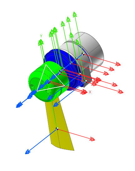
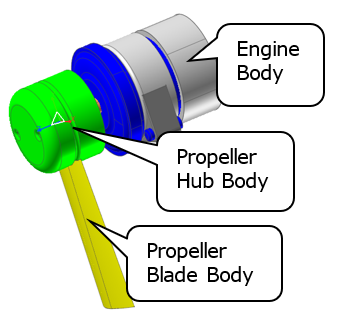
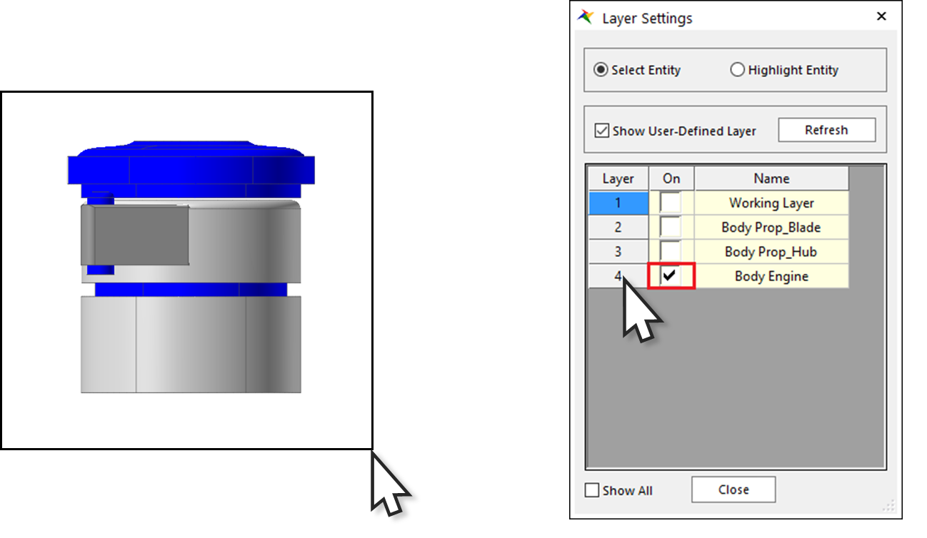
- Change the Layer number of newly imported eight bodies (ImportedBody5 ~ ImportedBody11 and NONE_4) into 4.The Working window should display the imported geometry as shown in the below figure.
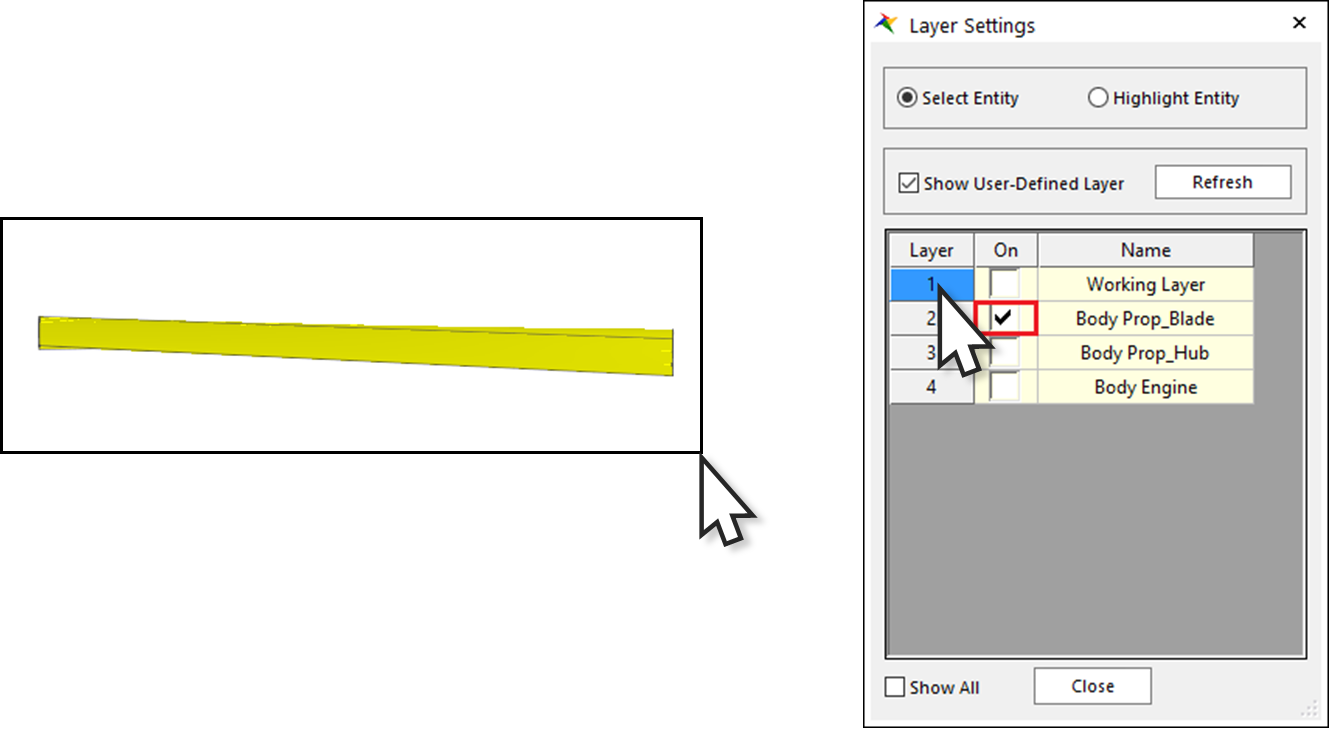
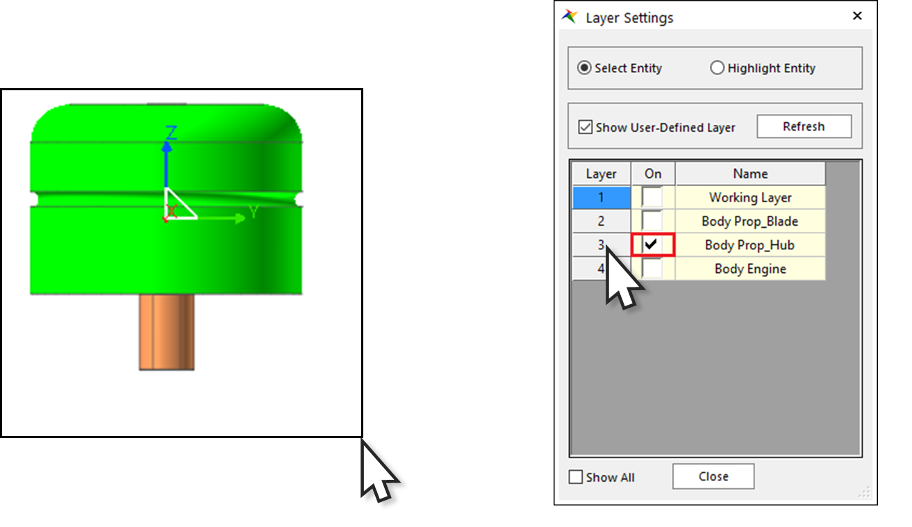
1.2.2.4.3. To Modify Layer Settings dialog
Click the Layer Settings tool at Render Toolbar. Layer Settings dialog will be indicated.
Check Show User-Defined Layer in order to see defined model’s layer only.
Change the name of layers like following.
Name of Layer1: Working Layer
Name of Layer2: Body Prop_Blade
Name of Layer3: Body Prop_Hub
Name of Layer4: Body Engine
Confirm whether Layer is matched well with each body by checking and unchecking the On checkbox.
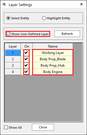
Click Close.
1.2.2.5. Adjusting the Icon and Marker Size
You are now going to change the icon and marker size to 20 pixels, so the icons do not obstruct the view of the model.
1.2.2.5.1. To change the icon and marker size:
Display the Icon Control dialog box by clicking the Icon Control tool in Render Toolbar. The Icon Control dialog box appears.
Set Icon Size and Marker Size to 20.
Clear the selection of All Markers.
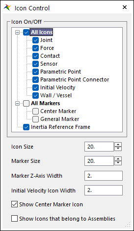
Close the Icon Control dialog box. (use the x in the upper right corner)
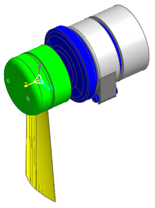
The graphics display changes from the one shown on the previous page to the one shown below.
Tip
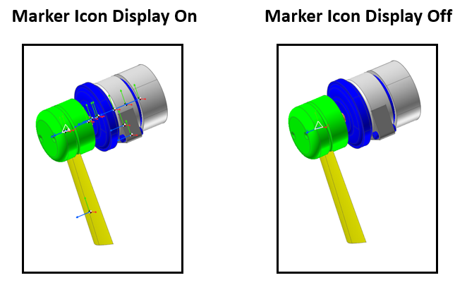
How to turn on/off the marker display
In addition to changing the size of marker and other entity icons, you can turn off the display of the icons.
1.2.2.6. Saving the Model
1.2.2.6.1. To save your model:
Take a moment to save your model before you continue with the next chapter.
From the File menu, click the Save function.
Enter a name and location for the file.
Click Save.
1.2.3. Organizing the Geometry
1.2.3.1. Task Objective
When you often import CAD geometry, RecurDyn translates it into a number of bodies that correspond to separated solids in the CAD model. However, these separate solids actually move together and should be merged together as a single body in RecurDyn.
For example, in Chapter 1, the import of the propeller blade resulted in the creation of two bodies and the import of the propeller hub resulted in the creation of two additional bodies. The two bodies from the propeller blade correspond to the blade supports and blade surface. The two bodies from the propeller hub correspond to the hub itself and a shaft.
For this model, you want the two imported bodies of the propeller blade to move together as a single RecurDyn body, and the respective imported bodies of the propeller hub and the engine to move as one. In this chapter, you will merge the imported bodies together to develop a RecurDyn model that you can work with efficiently.
1.2.3.2. Estimated Time to Complete
20 minutes
1.2.3.3. Merging the Imported Geometry
The table below shows the relationship between the bodies that you are going to work with in the RecurDyn model and the imported bodies. You will merge imported geometry to form the engine body, the propeller hub body and the propeller blade body. Each merged body has the combined mass properties of all of the solid geometry of the corresponding imported geometry.
Body Name |
Imported Geometry |
Prop_Blade |
ImportedBody1, ImportedBody2 |
Prop_Hub |
ImportedBody3, ImportedBody4 |
Engine |
ImportedBody5, NONE_4, ImportedBody6, ImportedBody7, ImportedBody8, ImportedBody9, ImportedBody10, ImportedBody11 |
1.2.3.3.1. To merge the propeller blade geometry:
The merge process consists of two steps. First you will select the bodies that are to be merged (Source Bodies). Second you will select the Target Body which will become the merged body that will contain all of the geometries of the Source Bodies as well as the geometry it previously had. It is allowable for the Target Body to be one of the Source Bodies and is typically convenient for that to be the case. Often the easiest method for selecting the Source Bodies is to draw a box that included the Source Bodies in the model window or Layer Setting dialog
Select the Change to YZ tool in Working Plane Toolbar.
Open Layer Settings dialog by clicking the Layer Settings tool at Render Toolbar.
Check On of only the Layer2 in order to see body which will be defined as Propeller blade.
Draw a box in the Working window that covers the left half of the propeller blade bodies or click Layer2 in Layer Settings as shown below.
The names of the bodies ImportedBody1 and ImportedBody2 will be selected in the Database window.
From the Tools group in the Home tab., click the Merge function. The Merge Body dialog box appears. ImportedBody1 and ImportedBody2 are selected.
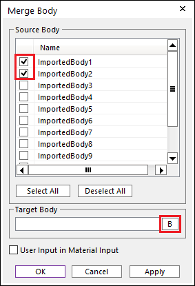
Click B in order to choose the Target Body.
To select the Target body, do one of the following:
In the Working window, click on the propeller. As you see ImportedBody2 will be selected, but it doesn’t matter if ImportedBody1 is selected instead.
OR
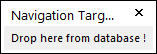
From the Database window, drag the name ImportedBody2 into the Navigation Target window which appears in the upper-right corner of the modeling window.
Click OK.
1.2.3.3.2. To merge the propeller hub geometry:
Activate On check of Layer3 only to see body which will be defined as a Propeller hub.
Select the hub and the shaft geometry as shown in the figure. The names of the bodies ImportedBody3 and ImportedBody4 will be selected in the Database window.
As before, select the Merge function. The Merge Body dialog box appears. ImportedBody3 and ImportedBody4 are selected.
Click B.
For the Target Body, select the propeller hub geometry (ImportBody3).
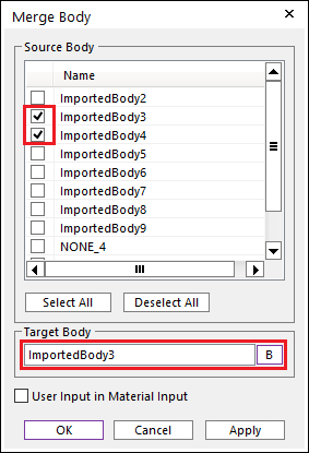
Click OK.
1.2.3.3.3. To merge the engine geometry:
Activate On check of Layer4 only to see body which will be defined as Engine.
Draw the selection box around the engine geometry as shown in the figure. The names of the bodies ImportedBody5 through ImportedBody11 will be selected in the Database window.
As before, select the Merge function. The Merge Body dialog box appears. ImportedBody5~ImportedBody11 and NONE_4 are selected.
Click B.
For the Target Body, select the lowest geometry on the engine (ImportedBody11).
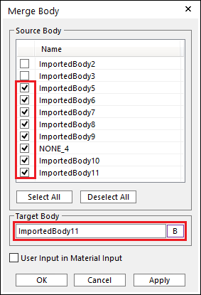
Click OK.
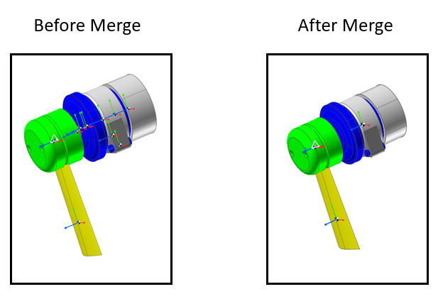
Active all of On checks in Layer Settings dialog to see entire entities.
Close Layer Settings dialog.
Notice that the number of markers is reduced because when the bodies were separate, they had one marker individually defining the center of their mass. Now that they are merged, there is only one body and one marker at the combined center of mass for each of the three remaining bodies, as shown in the figure below.
1.2.3.4. Renaming the Bodies
Now you will change the names of the three bodies so that you can more easily identify them.
1.2.3.4.1. To change their names:
In the Database window, right-click ImportedBody2.
From the menu that appears, select Rename.

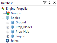
Type in the name Prop_Blade1.
- Following the procedure in Steps 1 - 3, change the name of body ImportedBody3 to Prop_Hub, and change the name of body ImportedBody11 to Engine.The list of bodies in the database window appears as shown below:
1.2.3.5. Creating a Second Propeller Blade
Now you will create a second propeller blade by copying the first blade.
1.2.3.5.1. To create a second propeller:
To copy the propeller in place, check and make sure the Shift when pasting option is turned off:
From the Settings group in the Home tab, click the General Setting function. The General dialog box will appear.
Make sure the Shift when pasting check box is not checked.
Click OK.
Rotate the image to get a front view of the propeller as follows: Select Change to XY.
In the Working window, select Prop_Blade1.
Tip
You can also place the cursor over the Prop_Blade1 name in the Database Window and click.
Now you can copy and paste the blade to create the second propeller blade. RecurDyn is a Windows application that supports several methods for copying and pasting.
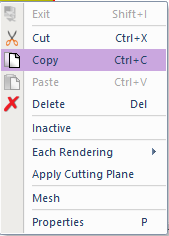
To copy the blade:
Type Ctrl+C key on the keyboard.
OR
From the Clipboard group in the Home tab, in, click the Copy function.
OR
In the Working Window, right-click and from the menu that appears, click Copy.
To paste the propeller, use the same techniques you used for copy (Ctrl+V key, click Paste or use the same menus as explained above).
You will not see the new blade because it shares the space of the original blade. However, there will be a new body entry in the Database window, C1_Prop_Blade1. Notice that in the Database window, RecurDyn prepends C1_ to the name of the original body to form the name of the new body.
1.2.3.6. Rotating the New Blade
You need to rotate the new blade, so it is on the opposite side of the engine axle from the original blade.
1.2.3.6.1. To rotate the blade:
On Advanced Toolbar, click the Basic Object Control tool to display the Basic Object Control dialog box. The Translate page is active.
Be sure the C1_Prop_Blade1 body (the new propeller) is selected.
Click the Rotate page in the Basic Object Control dialog box.
Change the value of the Degree field to 180.
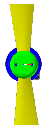
Click one of the Z Rotation tools to rotate the blade 180 degrees (either direction yields the same result.)
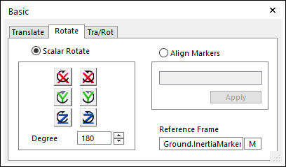
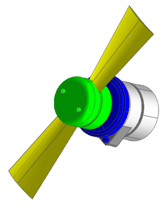
Your model should appear as shown in the figure.
Tip
How to rotate about different coordinate systems
The default in the Basic Object Control is to rotate an object about the global coordinate system (the default for the Reference Frame text box).If you need to rotate an object about an axis in a different reference frame, then click M and select the marker of interest.Close the Basic Object Control dialog box (use the x in the upper right corner).
Change the information of C1_Prop_Blade1 like following configuration by opening the General page in Properties dialog.
Name: Prop_Blade2
Layer: 2
1.2.3.7. Saving the Model
Take a moment to save your model before you continue with the next chapter.
Tip
From the File menu, click the Save function, or click the Save tool in the Quick Access Toolbar at the top of the RecurDyn window.
1.2.4. Creating Joints
1.2.4.1. Task Objective
In this chapter, you will create several joints. You will create:
One revolute joint to attach each propeller blade to the propeller
One cylindrical joint to attach the propeller hub to the engine
One fixed joint to fix the engine to ground
You will also define the rotation of the propeller.
1.2.4.2. Estimated Time to Complete
15 minutes
1.2.4.3. Attaching the Blades to the Hub with Revolute Joints
In this section, you will use revolute joints to attach the propeller blades to the propeller hub. You will first set the working plane and adjust the grid size. A grid size of 10 in each direction will make it convenient to use the grid and to locate some of the joints that you will define.
1.2.4.3.1. To set the working plane:
Set the working plane to the YZ Plane.
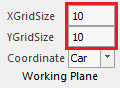
1.2.4.3.2. To change the grid size:
From the Working Plane group in the Home tab, set the following:
XGridSize: Input 10 and press the Enter key
YGridSize: Input 10 and press the Enter key
1.2.4.3.3. To attach Prop_Blade1 to the propeller hub:
From the Joint group in the Professional tab, click the Revolute Joint function.
Set the Creation Method to Body, Body, Point.

Click the Prop_Hub geometry.
Click the Prop_Blade1 geometry (on the left).
In the Input Window Toolbar, enter the point -5, -31, 6. (type the values, hit Enter key)

1.2.4.3.4. To attach Prop_Blade2 to the propeller hub:
Click Revolute again.
Keep the Creation Method as: Body, Body, Point
Click the Prop_Hub geometry.
Click the Prop_Blade2 geometry (on the right).
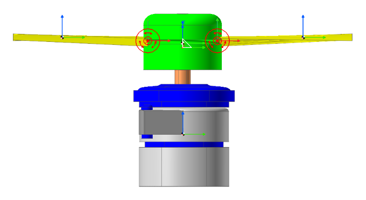
In the Input Window toolbar, enter the point -5, 31, 6. You should see the joint icons as shown in the figure below.
1.2.4.4. Attaching the Propeller Hub to the Engine
1.2.4.4.1. To attach the Prop_Hub body to the engine body with a cylindrical joint:
From the Joint group in the Professional tab, click the Cylindrical function.
Set the Creation Method to Body, Body, Point, Direction
Click the Engine geometry.
Click the Prop_Hub geometry.
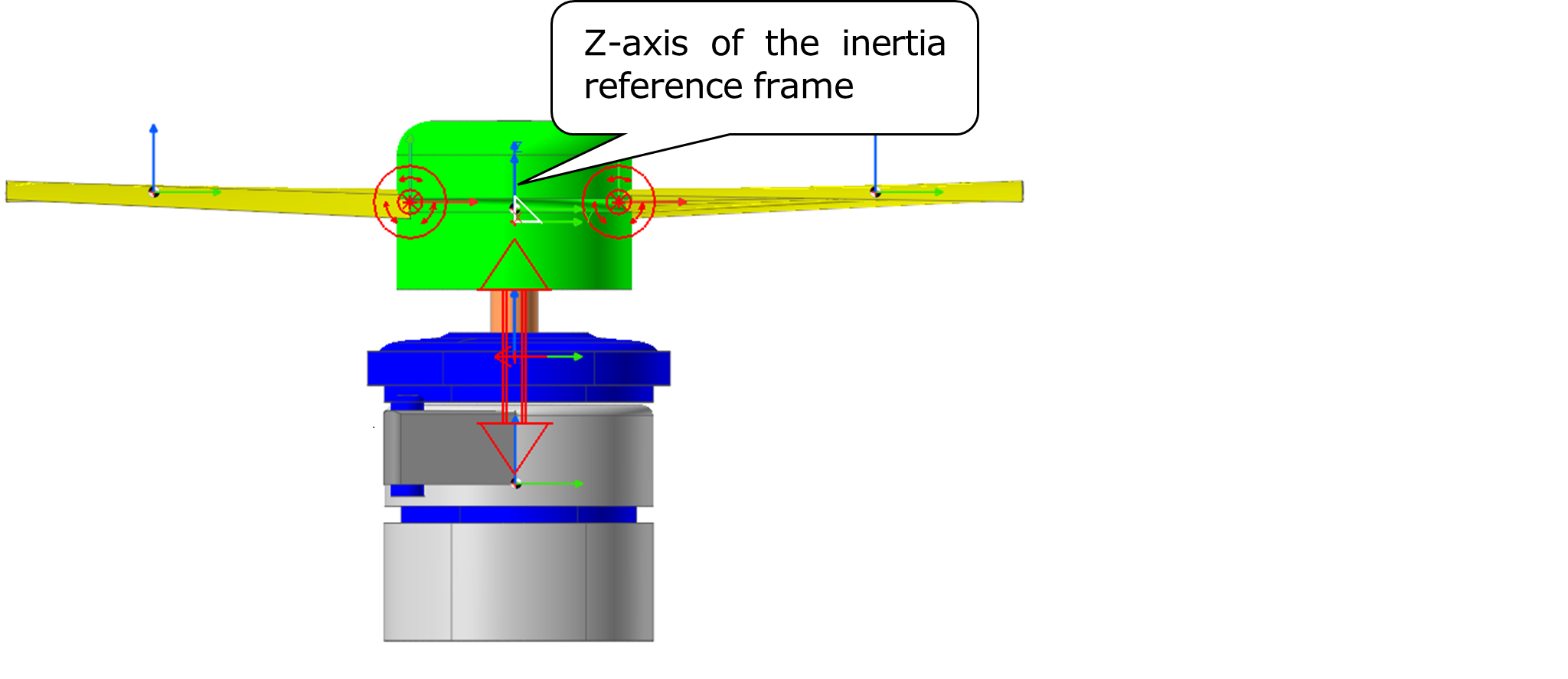
Click the point 0, 0, -40 in the Working window or enter 0, 0, -40 in the Input Window Toolbar.
To set the direction, click the Z-axis of the inertia reference frame (the blue arrow pointing up in the middle of the propeller hub).
1.2.4.5. Attaching the Engine to Ground with a Fixed Joint
1.2.4.5.1. To attach the engine body to ground with a fixed joint:
From the Joint group in the Professional tab, click the Fixed Joint function.
Set the Creation Method to Body, Body, Point.
To select Ground, click anywhere in the Working window where there is no geometry.
Click the Engine geometry.
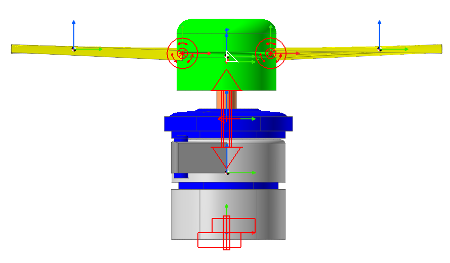
Click the point 0, 0, -120 in the Working window or enter 0, 0, -120 in the Input Window toolbar. You should see the joint icons as shown in the figure below.
1.2.4.6. Defining the Rotation of the Propeller
You will now define a constant acceleration of the propeller that begins 0.1 seconds after the simulation starts.
1.2.4.6.1. To define the rotation of the propeller:
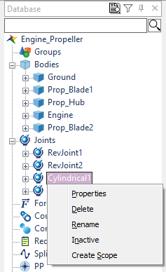
Display the Properties dialog box of the Cylindrical Joint.
Check Include Rotational Motion.
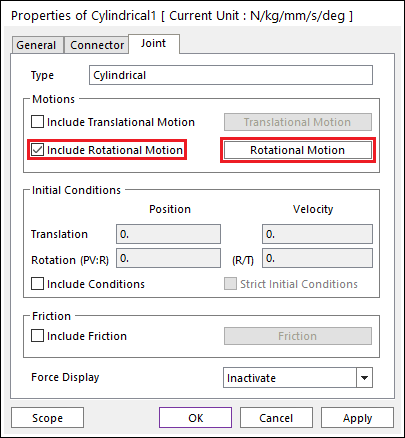
Click Rotational Motion. The Motion dialog box appears.
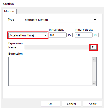
Set the menu labeled Displacement (time) to Acceleration (time).
Click EL. The Expression List dialog box appears.
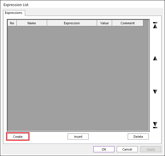
Click Create. The Expression dialog box appears.
To define a rotational acceleration of 10\(\pi\) radians/sec2 after 0.1 seconds of simulation time, enter the following expression in the large text box:
IF(TIME-0.1: 0, 0, 10*PI)
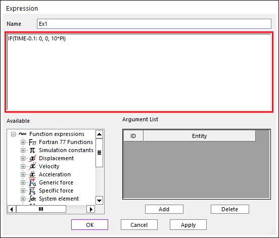
Click OK to exit the Expression dialog box.
Click OK to exit the Expression List dialog box.
Click OK to exit the Motion dialog box.
Click OK to exit the Cylindrical Joint Properties dialog box.
1.2.4.7. Saving the Model
Take a moment to save your model before you continue with the next chapter.
Tip
From the File menu, click the Save function.
1.2.5. Creating Forces
1.2.5.1. Task Objective
In this chapter, you will learn to create forces controlling the translation of the propeller and the local rotation of the propeller blades.
1.2.5.2. Estimated Time to Complete
10 minutes
1.2.5.3. Controlling the Translation of the Propeller
1.2.5.3.1. To create a translational spring force between the Prop_Hub and the engine:
From the Force group in the Professional tab, click the Spring Force function.
Set the Creation Method to Body, Body, Point, Point.
Click the Engine geometry.
Click the Prop_Hub geometry.
Click the point 0, 0, -80 in the Working window or enter the point 0, 0, -80 in the Input Window Toolbar.
Click the point 0, 0, -40 in the Working window or enter the point 0, 0, -40 in the Input Window Toolbar.
1.2.5.4. Controlling the Local Rotation of the Propeller Blades
To control the rotation of the propeller blades, you will create two rotational springs.
1.2.5.4.1. To create a torsion (rotational) spring between Prop_Hub and Prop_Blade1:
From the Force group in the Professional tab, click the Rotational Spring Force function.
In the Creation Method Toolbar, select Joint.
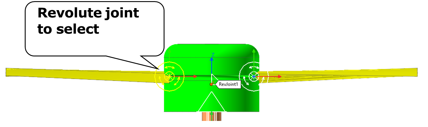
Click the Revolute Joint (RevJoint1) at Prop_Blade1 (on the left).
1.2.5.4.2. To create a torsion (rotational) spring between Prop_Hub and Prop_Blade2:
Select the Rotational Spring tool again.
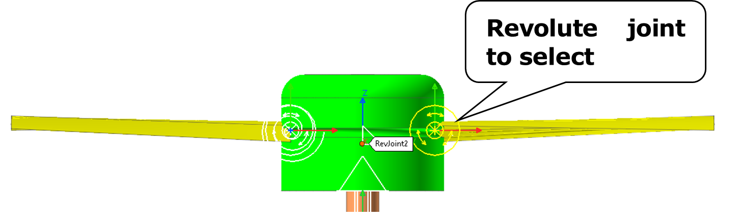
Click the Revolute Joint (RevJoint2) at Prop_Blade2 (on the right).
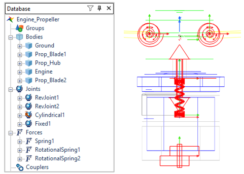
You should see the new force icons as shown in the next figure, as well as new joint and force entries in the Database window.
1.2.5.5. Saving the Model
Take a moment to save your model before you continue with the next chapter.
Tip
From the File menu, click the Save function.
1.2.6. Performing Analysis
1.2.6.1. Task Objective
In this chapter, you will run a simulation of the model you just created. You will rerun the simulation several more time later in the tutorial as you experiment with some changes to some of the model parameters.
1.2.6.2. Estimated Time to Complete
5 minutes
1.2.6.3. Performing Dynamic/Kinematic Analysis
You will run a dynamic/kinematic analysis to view the effect of forces and motion on the model you just created.
1.2.6.3.1. To perform a dynamic/kinematic analysis:
From the Simulation Type group in the Analysis tab, click the Dynamic / Kinematic Analysis function. The Dynamic/Kinematic Analysis dialog box appears.
Define the end time of the simulation and the number of steps:
End Time: 2
Step: 200
Plot Multiplier Step Factor: 5
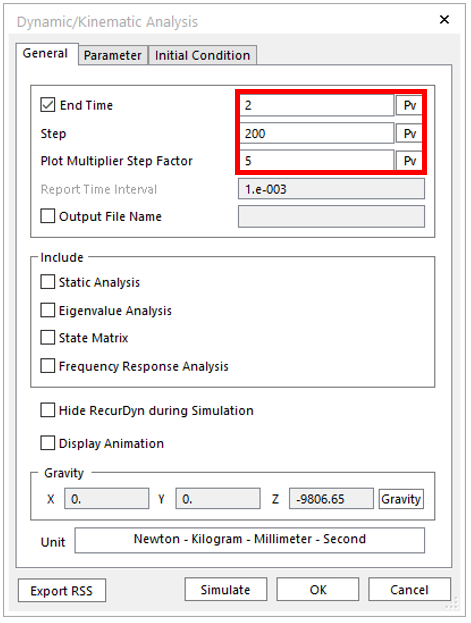
Click Simulate.
RecurDyn calculates the motions and forces acting on the engine with propeller model. There will be 1000 plot outputs stored because the number of steps is 200 and the Plot Multiplier Step Factor is 5.
Animate the model using the Play function on the Animation Control group in the Analysis tab. Refer to the 3D Crank Slider tutorial for more information on playing an animation.
Click the Stop function to reset the model.
1.2.7. Creating Scopes and Setting Force Display
1.2.7.1. Task Objective
Before you run another simulation, you will create output data scopes that let you view analysis results in small plotting windows as you animate the model. The scopes let you monitor angles, points, entities, and components of entities and with this model you will use them to monitor the local rotational motion of the blades. In addition, you will use the force display to monitor the forces at the revolute joints that attach the blades to the hub.
1.2.7.2. Estimated Time to Complete
10 minutes
1.2.7.3. Creating Scopes of Revolute Joint Rotation
You will create two scopes that measure the:
Rotation at RevJoint1, which connects Prop_Blade1 to the Prop_Hub
Rotation at RevJoint2, which connects Prop_Blade2 to the Prop_Hub
1.2.7.3.1. To create a scope on a joint:
From the Scope group in the Analysis tab, click the Entity Scope1 function. The Scope Entity dialog box appears.
Click Et and then click the RevJoint1 icon in the Working window, the icon for the revolute joint on the left side of the hub that connects Prop_Blade1 to the Prop_Hub body.
The name of the selected joint appears in the Entity Name text box.
The selection in the Component text box is Pos1_Relative. This is the rotational angle of the revolute joint and it is the output that you want. You do not need to change it.
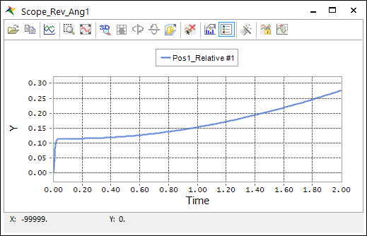
Change the name of the scope to Scope_Rev_Ang1.
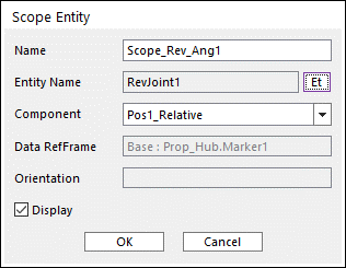
Click OK.
The scope plot appears with the angle rotation from the previous simulation. Note that the total rotation is small —only 0.3 degrees.
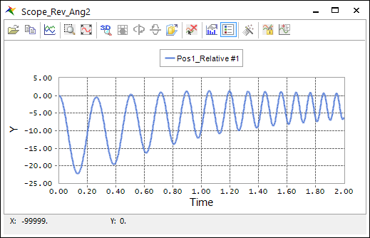
Now repeat Steps 1 - 5 with the changes needed to display the rotation of RevJoint2, naming the scope Scope_Rev_Ang2.
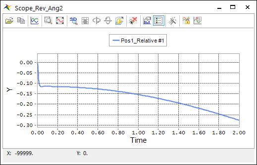
The second scope plot shows that the second revolute joint rotated the same amount as the first, but it has the opposite sign. The first blade rotates a small amount counterclockwise (about the Z-axis of the joint’s base marker) due to gravity, which is a positive rotation. The second blade rotates a small amount clockwise due to gravity, which is a negative rotation.
Tip
How to select an entity from the Database window
The Navigation Target window appears when you click the Et button while trying to create a scope. Rather than clicking on the entity icon in the Working window you could also drag the name of the entity in the database window to the Navigation Target Window in order to select that entity.
1.2.7.4. Setting Display of Forces
In this section, you will set up the display of the force in the translational spring along the propeller shaft during an animation.
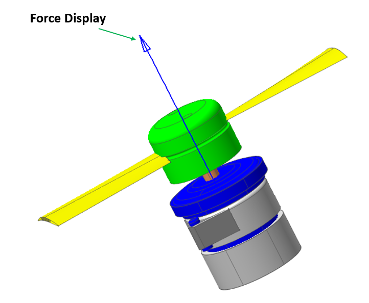
1.2.7.4.1. To set up the force display of the translational spring, Spring1:
Display the Properties dialog box for Spring1. The bottom item is the Force Display. Its default value is Inactive.
Set Force Display to Action.
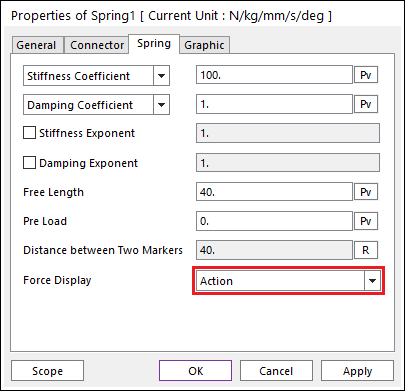
Click OK.
You will not see any difference if your graphics are in the shaded mode. You need to change them to the wireframe rendering to see the force vector.
Switch to the wireframe mode:
Right-click the Working Window.
From the menu that appears, point to Rendering Mode, and then click Wireframe with Silhouettes.
Now use the Play function on the Animation Control group in the Analysis tab to run the animation and look just above the coil spring on the propeller shaft for the force display. It will be a blue arrow pointing up. It spikes up a small amount and then quickly settles to a constant value (the weight of the propeller hub and blades).
Click the Stop function to reset the model.
Tip
Force Display
1.2.7.5. Saving the Model
Take a moment to save your model before you continue with the next chapter.
1.2.8. Performing a Design Study
1.2.8.1. Task Objective
Your model with the default spring parameters behaves in a very stiff manner. The motion of the propellers seems to suggest a rigid connection rather than a flexible connection. In this chapter, you will learn how to use RecurDyn to study the effect of stiffness and damping on the dynamic response of a mechanical system.
1.2.8.2. Estimated Time to Complete
15 minutes
1.2.8.3. Adjusting the Stiffness and Damping of Rotational Springs
You will use the two springs to study two factors:
With RotationalSpring1, you will reduce both the stiffness and damping by a factor of 100.
With RotationalSpring2, you will reduce the damping by an additional factor of 10.
1.2.8.3.1. To adjust the stiffness and damping of the rotational springs:
Display the Properties dialog box for RotationalSpring1.
Set the Stiffness to 100 and the Damping to 1 as shown below.
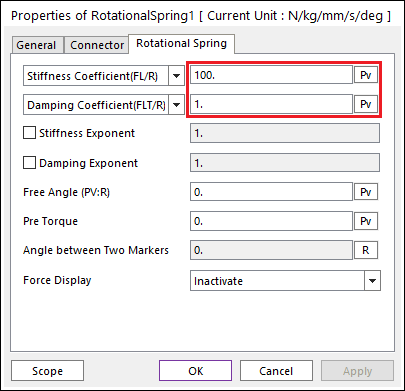
Click OK.
Display the Properties dialog box for RotationalSpring2.
Set the Stiffness to 100 and Damping to 0.1 (the same stiffness but lower damping).
Click OK.
1.2.8.4. Running a New Analysis
You are ready to run a simulation with the modified spring parameters. As you run the simulation, you will adjust a few simulation parameters to get the best answer for this model.
1.2.8.4.1. To run a new analysis with the modified spring parameters:
From the Simulation Type group in the Analysis tab, click the Dynamic / Kinematic Analysis function.
The Dynamic/Kinematic Analysis dialog box appears. Notice that the end time of the simulation and the number of steps have the values that you set in the first simulation. Therefore, you need to make no changes in the first tab.
Click the Parameter page and set:
Maximum Time Step: 0.001
Numerical Damping: 0.1
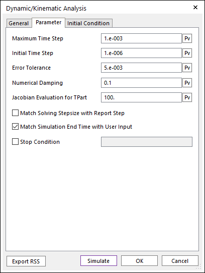
The default values for Maximum Time Step and Numerical Damping work well for many practical problems that have many parts and high stiffness. For this model, you change them because:
Numerical Damping is applied at the system level and helps a model simulate smoothly when there is no damping defined for degrees of freedom at the joints. In this model, you have damping defined for each degree of freedom and you are studying the effect of reducing the spring damping. In this case, it is a good practice to reduce the Numerical Damping from 1.0 to 0.1.
The Maximum Step Size is reduced because the numerical integrator in RecurDyn will take large steps with such a simple model that exhibits smooth motion. A smaller maximum time step is appropriate because you want to capture the gradual decay of the blade motion.
Click Simulate. The simulation will run in a few seconds.
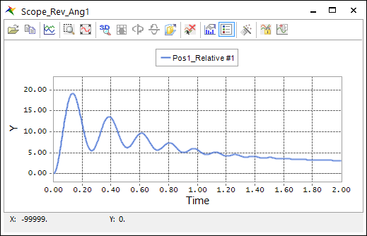
You will see some significant changes in the data shown on the two scopes. Both blades are moving through approximately 20 degrees of initial rotation. There is much more oscillation in blade motion. Now is a good time to animate the model to observe the behavior that is suggested by the plots.
Use the play function on the Animation Control group in the Analysis tab to display the animation as explained in the beginning tutorial.
Click the Stop function to reset the model.
1.2.8.5. Questions to Consider from the Design Study Results:
Here are a few questions. The answers are provided later.
Why did the blades move through a larger displacement in the second simulation?
Why did the blades oscillate more in the second simulation?
Why did Prop_Blade2 oscillate more than Prop_Blade1?
Why does the magnitude of the average rotation of the blades decrease in the later portions of the simulation?
How could you check for the accuracy of the solution?
Answers to the questions:
Reduced stiffness in the rotational springs.
Reduced damping in the rotational springs.
Reduced damping in rotational spring #2.
As propeller spins at a higher rotational velocity the centripetal acceleration increases and tends to offset the effects of gravity.
Set the Maximum Time Step to 0.0001 (10x lower) and run the simulation again. Since the results are the same you can have confidence in the accuracy of the results.
1.2.8.6. Ideas for Further Exploration:
You obtained interesting changes to the model results by changing the stiffness and damping values of the rotational spring.
How could you change the values of stiffness and damping in the coil (translational) spring?
Think about the experimentation process. You may have a hard time to recognize which change in which variable caused the changes of the output if you change the stiffness and the damping at the same time.
What change in response would you expect if you changed the gravity to act in the –Y direction? Make the change and see if you were correct.
You can change the direction of the gravity vector by using the Gravity command in the Settings menu.
1.2.9. Plotting the Results
1.2.9.1. Task Objective
In this chapter, you will plot the analysis data that RecurDyn calculated in the dynamic/kinematic simulation you ran in the previous chapter. You will plot and work with the rotational output of the revolute joints, using the RecurDyn plotting tool. It lets you plot and animate the results of simulations.
1.2.9.2. Estimated Time to Complete
10 minutes
1.2.9.3. Creating a Plot
In this section, you will start RecurDyn/Plot.
1.2.9.3.1. To start RecurDyn/Plot:
From the Plot group in the Analysis tab, click the Plot Result function. The Plotting window appears with all the tools and data that you need.
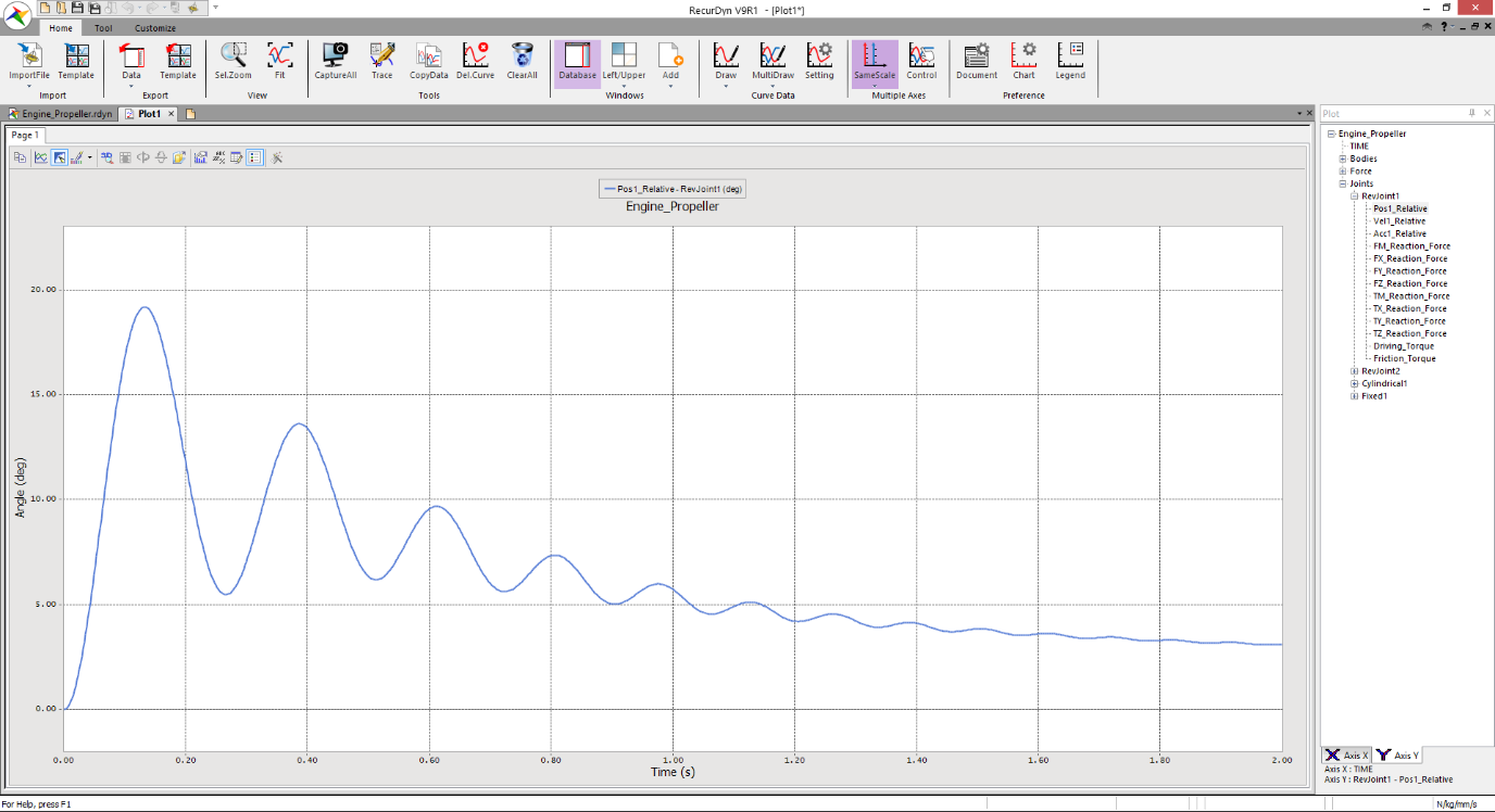
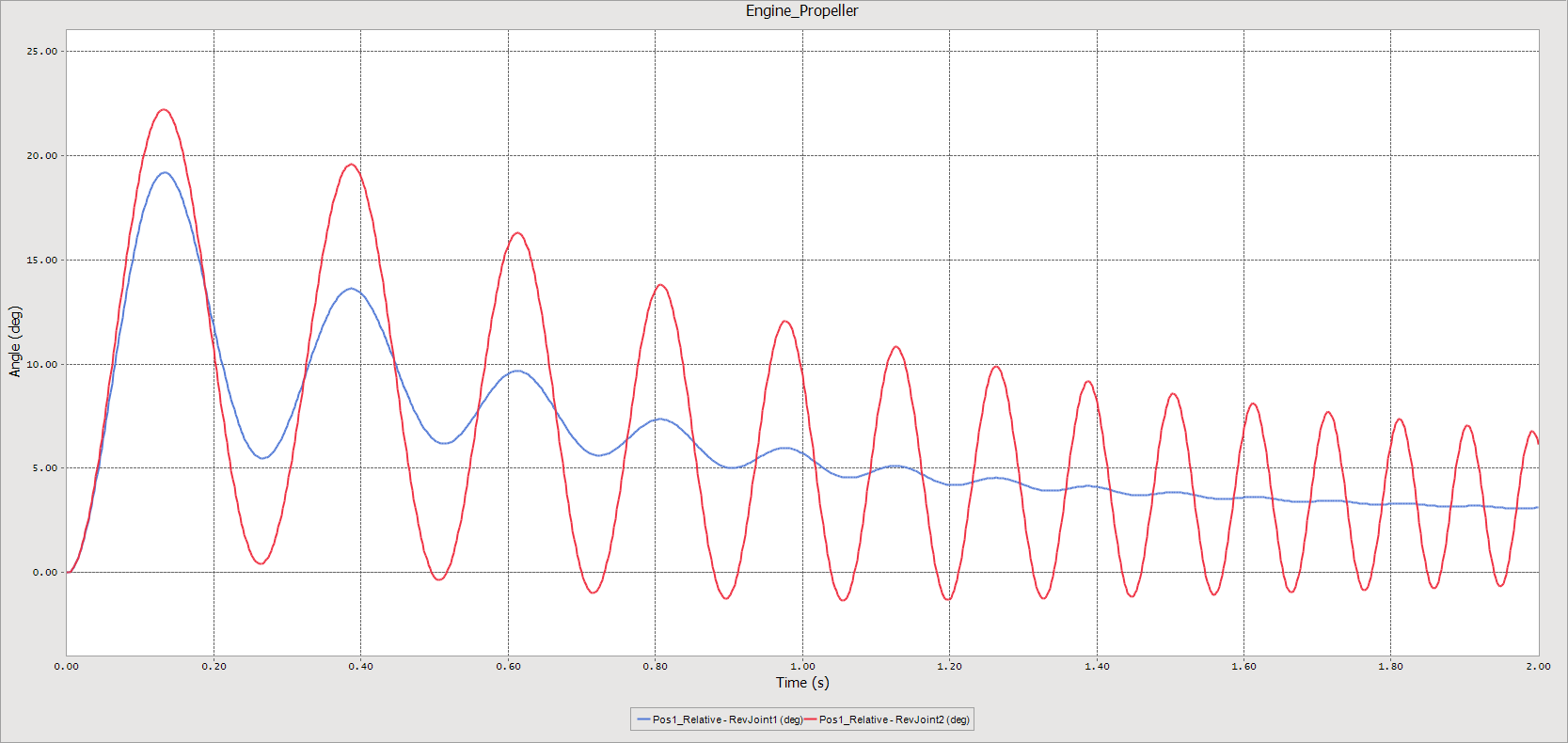
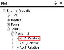
In the Plot Database window, click the + in front of Joints and RevJoint1, and then double-click Pos1_Relative to display the rotation of Prob_Blade1 (same as the first scope).
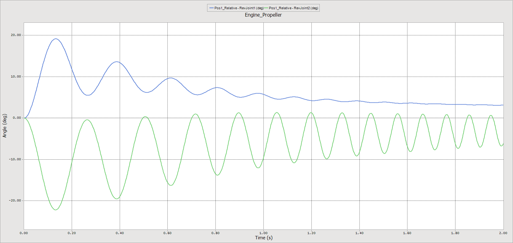
Click RevJoint2, and then double-click Pos1_Relative to display the rotation of Prob_Blade2 (same as the second scope).
The plot appears as shown next. It contains both curves of the two scopes in the same plot. It would be beneficial to be able to compare the two blade rotations, but the comparison is difficult because one curve has negative values and the other curve has positive values. You will use the analysis capability in the plotting tool to make this comparison easier.
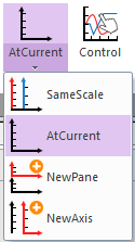
Before using the Simple Math tool to draw the curves at the same axis, check and make sure the At Current Axis function is turned on. (Current Axis function is in Multiple Axes group of Home tab)
From the Analysis group in the Tool tab, click the Math function. The Data Analysis dialog box appears.
Click on the field to the right of the Math Type field, to display the dropdown menu button.
Select the Math Type to Scale:alpha*F1.
Set the Source Curve1 (F1) to the second curve, Pos1_Relative – RevJoint2 (deg).
Set Y Scale Factor to -1.
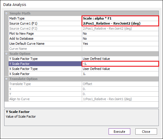
Click Execute.
Click Close.
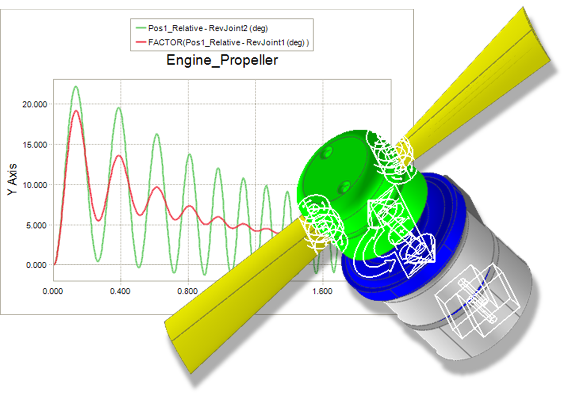
A new curve (FACTOR(Pos1_Relative - RevJoint2 (deg))) appears on the plot that represents the absolute value of the Blade2 rotation.
On the plot, click on the original Blade2 rotation curve (Pos1_Relative - RevJoint2 (deg), with negative values) and you should see the curve become highlighted.
Press the Delete key on your keyboard to delete the curve.
OR
From the Tools group in the Home tab, click the Delete Curve function.
Click Yes when prompted to confirm the deletion of the curve.
Click Fit to adjust the curves.
From the Preference group in the Home tab, click the Legend function. The Legend Title dialog box appears.
Change the Legend #2 title name to Pos1_Relative - RevJoint2 (deg).
Click OK. The legend title is changed.
In the legend box, right-click and from the menu that appears, click Bottom.
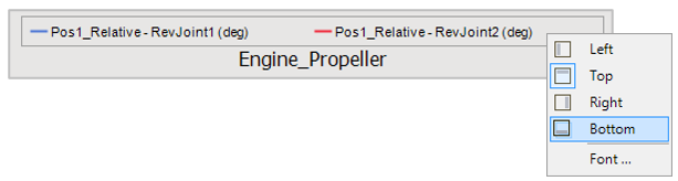
The plot should now appear as shown below.