9.9. Media Transport Toolkit 3D Tutorial (MTT3D)
9.9.1. Getting Started
9.9.1.1. Objective
This tutorial introduces you to the special capabilities of the Media Transport Toolkit 3D (MTT3D). MTT3D allows you to model sheets progressing through complex paper paths in three dimensions, allowing you to study 3D phenomena such as sheet corrugation and misalignment. In this tutorial, you will examine sheet corrugation in part of a printer device.
9.9.1.2. Model Used
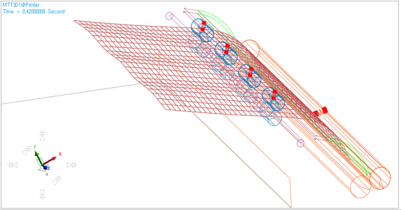
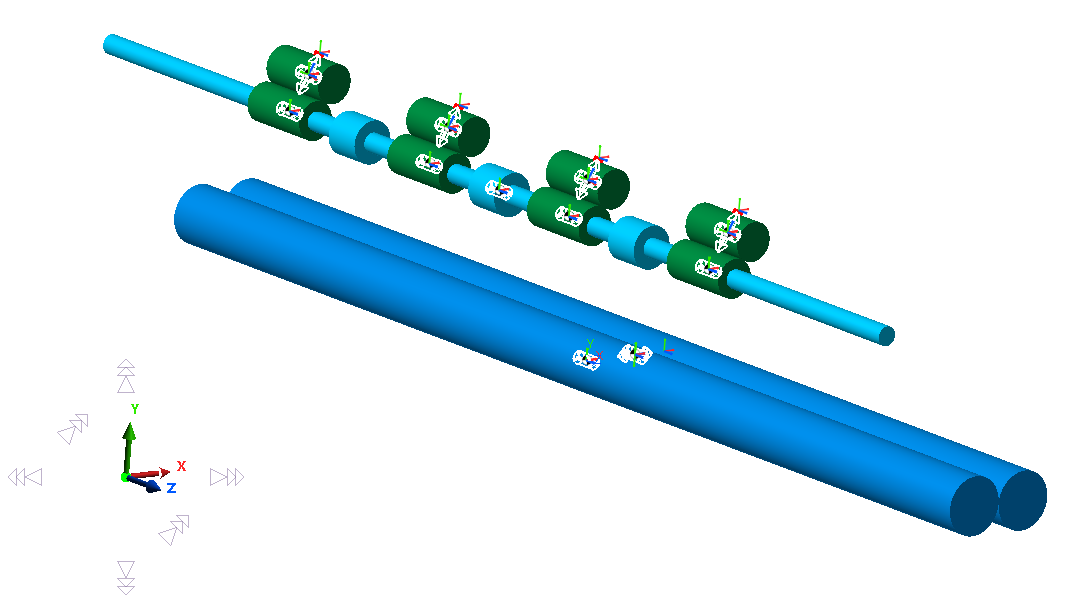
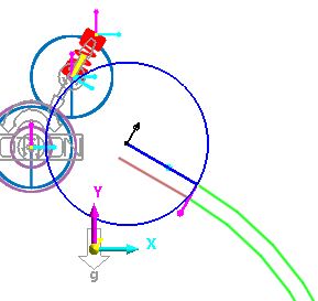
The model used in this tutorial is the final portion of the paper path of a laser printer, namely the path that the sheet passes through before landing in the tray. To prevent paper jams and allow for an orderly stack of sheets in the output tray, a special multi-profile roller is used to corrugate the sheet to keep it straight before falling into the tray. The corrugation of the paper prevents the leading edge of the sheet from hanging down and dragging along the surface of the tray (or the sheets that are already in the tray). A side view of the model is shown below.
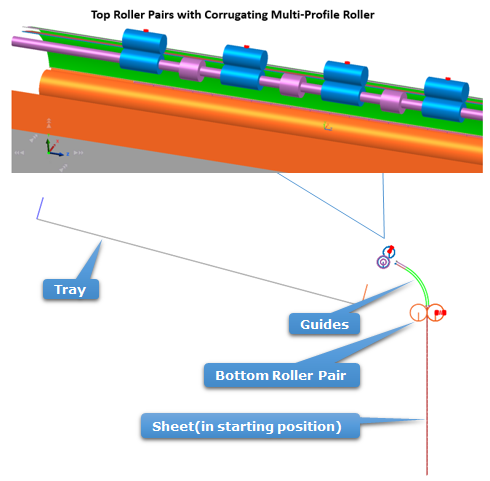
As shown below, the corrugation roller works because the blue rollers have a larger radius than the lower purple rollers which rotate about the same axis. Therefore, the blue rollers push the sheet upwards in between the purple roller pairs, distorting the sheet.
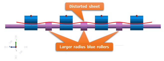
If the corrugation effect is strong enough, the folds in the sheet cause it to resist gravity-induced bending, allowing the sheet to remain straight as it exits the printer, as shown below.
Due to the limited time you may have to complete this tutorial, the rest of the printer is not modeled. Also, to simplify the model further, the sheet used is half the size of a standard A4 sheet. Since the sheet is modeled as a mesh, this reduces the number of sheet bodies.
9.9.1.3. Audience
This tutorial is intended for experienced users of RecurDyn. All new tasks are explained carefully.
9.9.1.4. Prerequisites
Users should first work through the 3D Crank-Slider, Engine with Propeller, and Pinball (2D contact) tutorials, or the equivalent. We assume that you have a basic knowledge of physics.
9.9.1.5. Procedures
The tutorial is comprised of the following procedures. The estimated time to complete each procedure is shown in the table below.
Procedures |
Time (minutes) |
Creating the Model |
30 |
Running a Simulation |
10 |
Modifying the Design |
10 |
Total |
50 |
9.9.1.6. Estimated Time to Complete
50 minutes
9.9.2. Creating the Model
9.9.2.1. Task Objective
Learn how to define rollers, guides, and sheet bodies.
9.9.2.2. Estimated Time to Complete
30 minutes
9.9.2.3. Creating a New Model and MTT3D Subsystem
9.9.2.3.1. To create a new model:
On your Desktop, double-click the RecurDyn tool. RecurDyn starts and the Start RecurDyn window appears.
Enter Printer as the Model Name.
Select OK.
9.9.2.3.2. To create a new MTT3D subsystem:
From the Subsystem Toolkit group in the Toolkits tab, click the MTT3D function.
RecurDyn will bring you into the new MTT3D subsystem, and a new MTT3D tab will appear in the ribbon for the MTT3D functions.
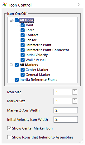
9.9.2.3.3. To adjust the Icon Size in the model:
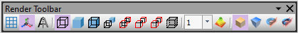
From Render Toolbar, select the Icon Control tool.
Change both the Icon Size and Marker Size from the default value of 10 to 3.
9.9.2.3.4. To set the render mode to Wireframe:
From Render Toolbar, select the Wireframe tool.
9.9.2.4. Creating the Bottom Rollers
You will now create the bottom roller pair in which the sheet starts.
9.9.2.4.1. To create the bottom roller pair:
From the Roller group in the MTT3D tab, click the Pair Roller function.
Select the point 0, 0, 0 in the Working Window to define the center of the fixed roller or type the values into in the Input Window Toolbar.
Enter 7.5 in the Input Window Toolbar and press the Enter key to set the radius of the fixed roller.
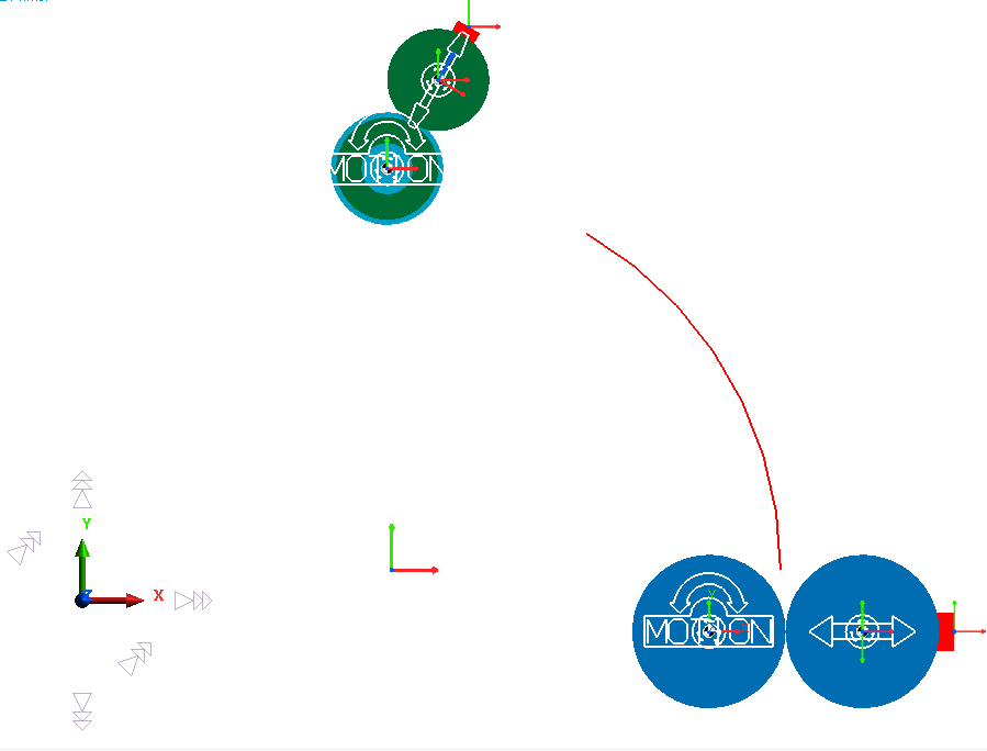
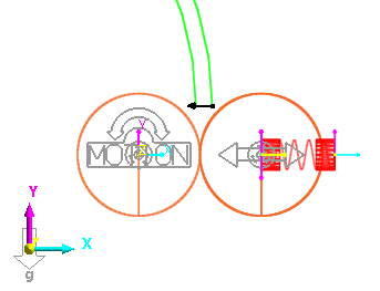
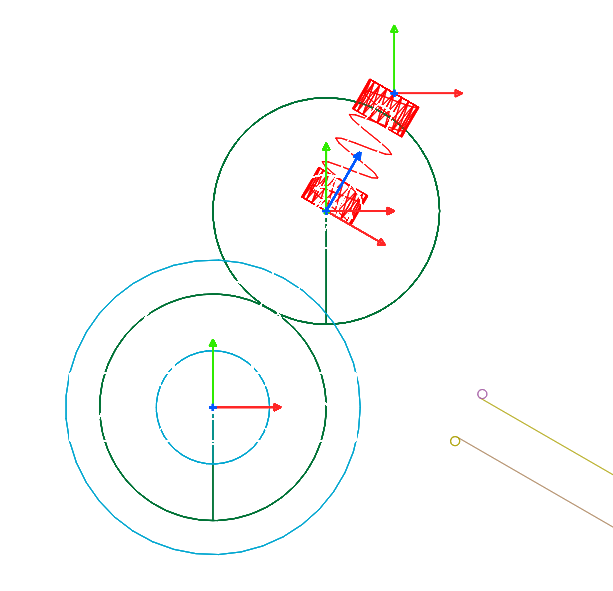
Select the +X direction, by clicking on a point directly to the right of 0, 0, 0. The arrow which indicates the direction that will be selected should point directly to the right, as shown at below.
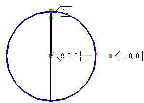
Enter 7.5 in the Input Window Toolbar to set the radius of the movable roller.
You will now modify the bottom roller pair to have the correct properties.
9.9.2.4.2. To edit the bottom fixed roller:
From the Database Window, open the Properties window for MTT3D1 > Groups > FixedRollerGroup1.
To the right of Contact Parameter, select the To Sheet button.

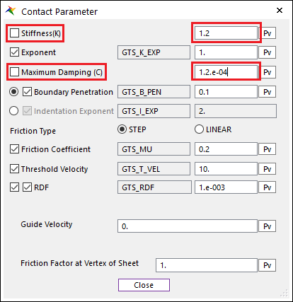
Make the following settings:
Stiffness: 1.2
Maximum Damping: 1.2e-4
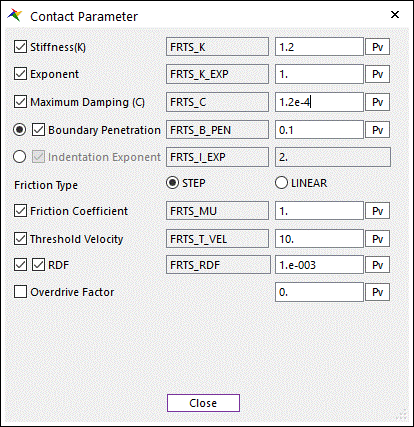
Note
If the checkboxes next to a parameter is checked, the value displayed will be considered a Special Parametric Value (SPV) and be used for all other fixed rollers in the model which have the same checkbox checked. There are separate sets of SPVs for movable rollers and other model entities.
Note
Here, you increased the contact stiffness to prevent the roller from penetrating the sheet excessively, as you will be increasing the nip spring stiffness of the opposing roller from its default value later. Excessive contact penetration reduces the accuracy of the simulation. At the same time, increasing contact stiffness too much will slow down the simulation. Therefore, a general rule of thumb is to allow for penetration which is ~25% the thickness of the sheet.Also, the damping was increased by the same factor as the stiffness.When adjusting stiffness and damping values, a good practice is to start with the default values and scale them both by the same factor.If necessary, they can be adjusted individually later.Select Close.
Select OK.
9.9.2.4.3. To edit the bottom movable roller:
From the Database Window, open the Properties window for MTT3D1 > Groups > MovableRollerGroup1.
Select Nip Spring Property.
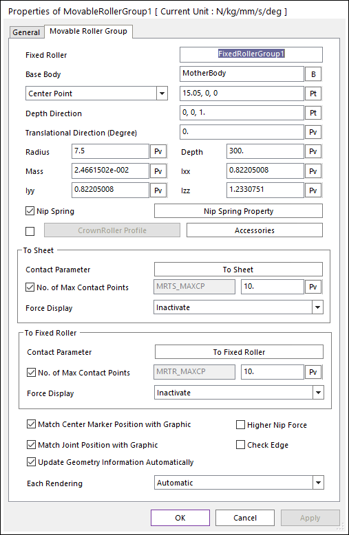
Uncheck the boxes next to Stiffness, Damping, and Pre Load.
Note
By unchecking the boxes, you are specifying that the parameter values set for this roller will not be linked to the Special Parametric Values used for other movable rollers in the model.
Make the following settings as shown below.
Stiffness: 0.1
Damping: 1e-2
Pre Load: 0.5
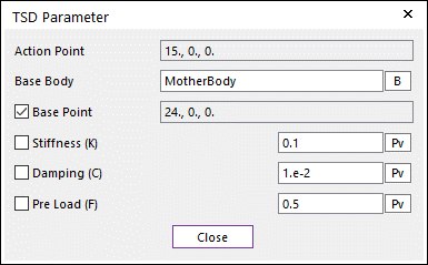
Click Close to return to the Properties of MovableRollerGroup1 dialog.
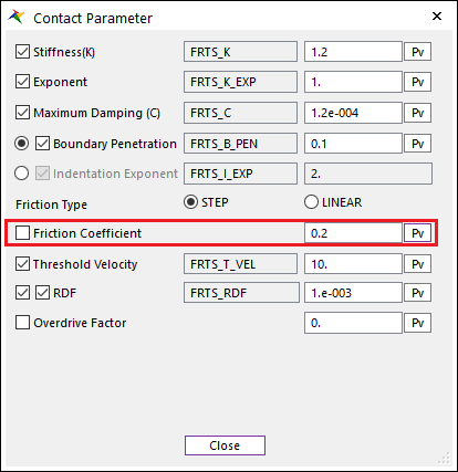
To the right of Contact Parameter, select the To Sheet button.
Make the following settings as shown at below.
Stiffness: 1.2
Maximum Damping: 1.2e-4
Friction Coefficient: 0.2
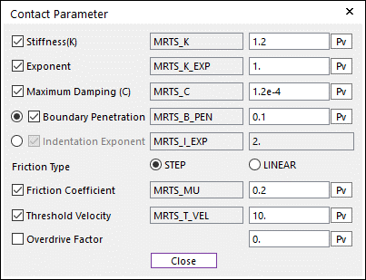
Note
A lower friction coefficient of 0.2 was chosen for this movable roller, because we want to model its surface as plastic. The default friction coefficient of 1.0 was used for the fixed roller, on the other hand, because we want to model its surface as being rubberized so it can grip the sheet.
Click Close.
Click OK.
9.9.2.5. Creating the Top Rollers
You will now create the top rollers, starting with the first top roller pair, which will be duplicated three times for a total of four roller pairs on top.
9.9.2.5.1. To create the first top roller pair:
Select the Pair Roller function from the Roller group under the MTT3D tab in the ribbon.
Enter the point -31.446, 45.228, 81 in the Input Window Toolbar for the center of the fixed roller.
Enter a radius of 5 in the Input Window Toolbar for the fixed roller.
Enter a direction of 1, 1.7321, 0 in the Input Window Toolbar to specify the movable roller location.
Enter a radius of 5 in the Input Window Toolbar for the movable roller.
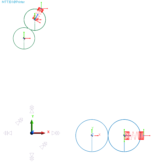
At this point, your model should appear as shown below.
You will now edit the top roller pair to have the correct properties before duplicating it.
9.9.2.5.2. To edit the first top fixed roller:
From the Database Window, open the Properties window for MTT3D1 > Groups > FixedRollerGroup2.
Enter a Depth of 20.
Check the box next to Check Edge in the lower right of the dialog box.
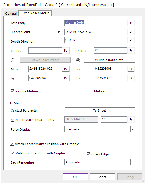
Click OK.
Note
The Check Edge option should be selected when a roller’s radius is smaller than the length of an individual element in the sheet mesh. When this condition occurs, the contact between the ends of the roller and the sheet must be taken into account.
9.9.2.5.3. To edit the first top movable roller:
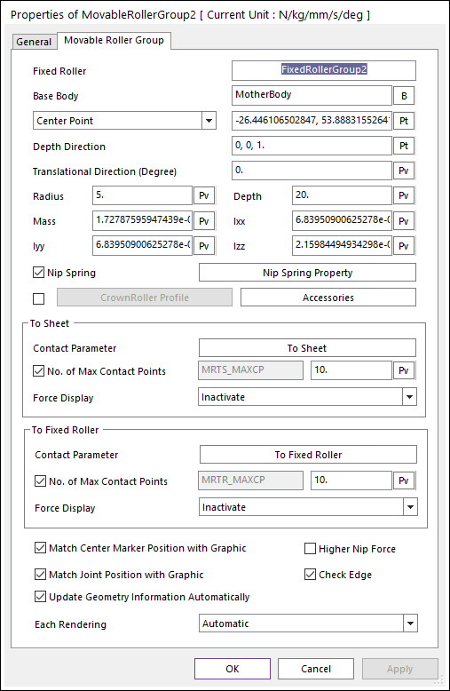
From the Database Window, open the Properties window for MTT3D1 > Groups > MovableRollerGroup2.
Enter a Depth of 20.
Check the box next to Check Edge.
Select Nip Spring Property.
Make the following settings as shown at below.
Stiffness: 1e-2
Damping: 1e-3
Pre Load: 5e-2
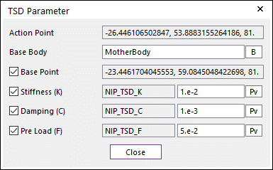
Click Close.
Click OK.
Because the top movable rollers are small, spring mounted, and their rotation is not specified with a motion input, their behavior is highly influenced by the sheet and the corresponding fixed roller. Because of this, it is important to set the mass and inertia properties to reasonable values to ensure accurate results. In our model, we will specify that the roller is made of Nylon.
9.9.2.5.4. To edit the mass properties of the first top movable roller:
To bring up the Properties dialog for the body MovableRollerBody2 and not the group MovableRollerGroup2.
In the Database Window, locate but do not click on MTT3D1 > Bodies > MovableRollerBody2.
Without selecting it first, right-click on MovableRollerBody2, and select Properties as shown at below.
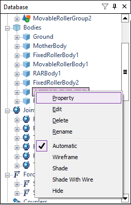
Select the Body page.
For Material Input Type, select Library. Click OK on the warning dialog that pops up.
For Material Type, select Nylon.
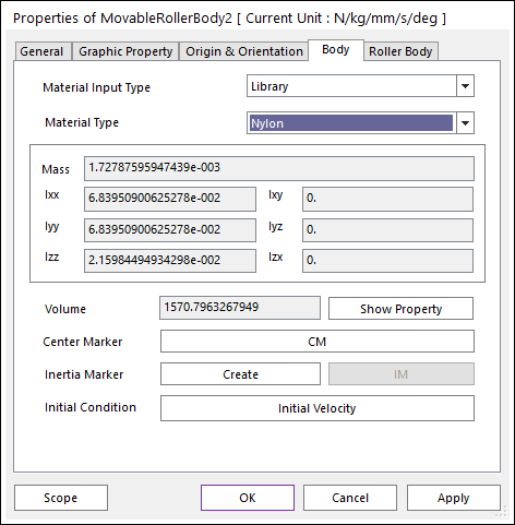
Click OK.
The roller pair is ready to be duplicated. But first, you will want to change some of the program user settings to make copying and pasting easier.
9.9.2.5.5. To change the program user copy/paste settings:
From the Home tab in the Ribbon, select the General Setting function in the Setting group.
Uncheck the box next to Shift when pasting.
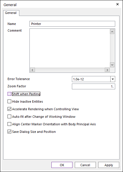
Click OK.
You will now make copies of the second roller pair and array them through the -Z direction to create the row of top driving roller pairs.
9.9.2.5.6. To duplicate the first top roller pair:
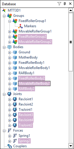
In the Database Window, select both FixedRollerGroup2 and MovableRollerGroup2:
First select FixedRollerGroup2.
Then hold down the Ctrl key and select MovableRollerGroup2.
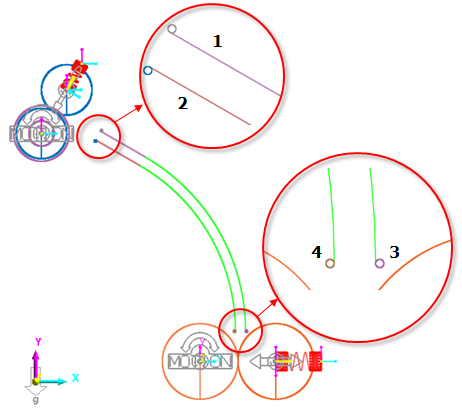
The associated bodies, joints, and forces will be selected automatically as shown at below.
From the Clipboard group from the Home tab, select the Copy function. (Or press Ctrl+C key.)
From the Clipboard group from the Home tab, select the Paste function. (Or press Ctrl+V key.)
Repeat the previous step (Paste) twice, so that there are a total of four identical roller pairs.
9.9.2.5.7. To move the duplicated roller pairs into place:
In the Database Window, use the Ctrl key to select C1_FixedRollerGroup2 and C1_MovableRollerGroup2.
From Advanced Toolbar, select the Basic Object Control tool.
For the Offset Value, enter 54.
Click the -Z button.
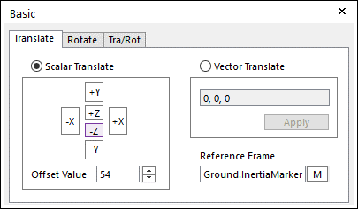
The first copy of the nip pair should have been translated 54 mm in the -Z direction.
In the Database Window, use the Ctrl key to select C2_FixedRollerGroup2 and C2_MovableRollerGroup2.
In the Basic Object Control dialog, click -Z twice to move it 108 mm in the -Z direction.
In the Database Window, use the Ctrl key to select C3_FixedRollerGroup2 and C3_MovableRollerGroup2.
In the Basic Object Control dialog, click -Z three times to move it 162 mm in the -Z direction.
9.9.2.5.8. To create the multi-profile corrugating roller:
Select the Fixed Joint function from the Roller group under the MTT3D tab in the ribbon.
Enter -31.446, 45.228, 0 into the Input Window Toolbar as the roller center.
Enter a radius of 2.5 in the Input Window Toolbar for the fixed roller.
Open the Properties window of FixedRollerGroup3.
Check the box next to Check Edge.
Click Multiple Roller Info..

Click Add three times and enter the following roller data as shown at below.
Radius
Depth
Distance
5.5
10
-54
5.5
10
0
5.5
10
54
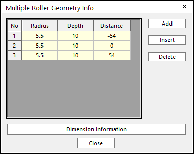
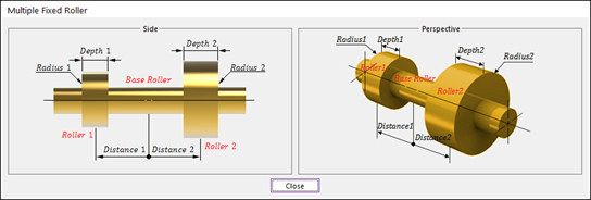
Note
To understand how the above variables apply to the rollers, click Dimension Information to display the diagram shown at above. When finished, click Close to close the window.
Click Close.
To the right of Contact Parameter, click To Sheet.
Uncheck the box next to Friction Coefficient.
Enter a Friction Coefficient of 0.2.
Click Close.
Click OK. Your model should appear as shown below (rotated and rendered in the Shaded mode).
Save your model.
9.9.2.6. Adding Motion to the Fixed Rollers
You will now add motion to the fixed rollers, defining expressions which will ramp the rotational velocity up from zero to end values which will move the sheet at a linear velocity of 400 mm/sec. The end values will differ depending on the radius of the roller, but you will enter the expressions in such a way that RecurDyn will perform the calculations for you.
9.9.2.6.1. To add motion to the bottom fixed roller:
From the Database Window, open the Properties window for MTT3D1 -> Groups -> FixedRollerGroup1.
Check the Include Motion checkbox and select the Motion button next to it.

Choose Velocity (time) from the dropdown as the variable to control.
Select EL to open the Expression List dialog.
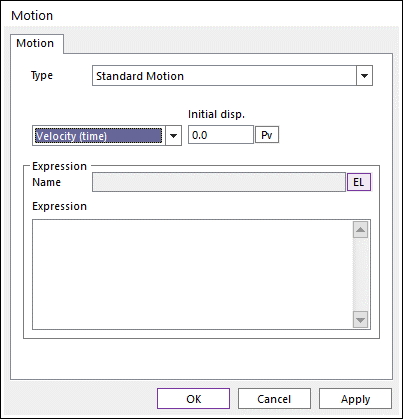
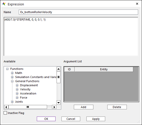
Select Create to create a new expression.
As shown below, enter a Name of Ex_bottomRollerVelocity.
Enter the following expression, which references the desired velocity and the roller radius:
(400/7.5)*STEP(TIME, 0, 0, 0.1, 1)
Select OK four times.
9.9.2.6.2. To add motion to the top fixed rollers:
From the Database Window, use the Ctrl key to select the following.
FixedRollerGroup2
C1_FixedRollerGroup2
C2_FixedRollerGroup2
C3_FixedRollerGroup2
Right-click on one of the items and select Properties.
Check the box next to Include Motion and select Motion.
Choose to control Velocity (time) from the dropdown.
Select EL to open the Expression List dialog.
Select Create to create a new expression.

As shown above, enter a Name of Ex_topRollerVelocity.
Enter the following expression:
(400/5) * STEP(TIME, 0, 0, 0.1, 1)
Click OK four times.
9.9.2.7. Creating the Guides
You will now create the arc, linear, and edge guides which the sheet will proceed through.
9.9.2.7.1. To create the inner arc guide:
Return to view the standard X-Y plane. (Shortcut is the Shift+X key.)
Select the Arc Guide function from the Guide group under the MTT3D tab in the ribbon.
In the Input Window Toolbar, enter a center point of -31, 6.
Enter a start point of 7, 6.
Enter a reference direction of 0, 1.
Enter an angle of 60 degrees.
The first guide should now appear as shown at below. (You will duplicate this inner guide later to create an outer guide.)
From the Database Window, select MTT3D1 > Guides > GuideArc1, and open the Properties dialog.
Check the box next to Check Edge.
To the right of Contact Parameter, select To Sheet.
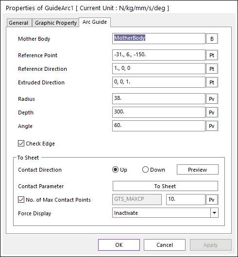
Set the Friction Coefficient to 0.2.
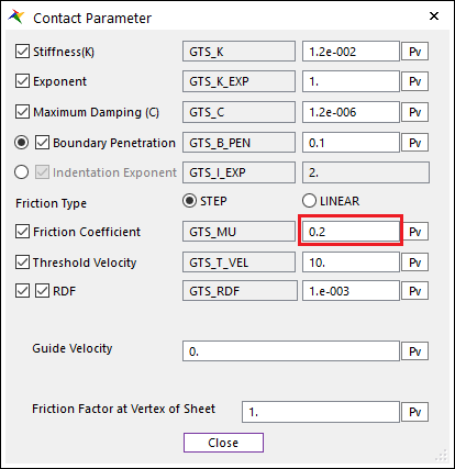
This will set the default friction coefficient for all guides to this value.
You will now adjust the contact direction to ensure that it points in the correct direction.
Back in the Properties of GuideArc1 dialog, to the right of Contact Direction, click Preview. Click Up.
A small arrow indicating the direction of contact should appear, as shown at below.
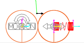
Press the Esc key to exit the preview mode.
If the arrow did not point in the direction shown at above, change the Contact Direction using the Up and Down radio buttons.
Click OK to exit the Properties window.
9.9.2.7.2. To create the outer arc guide:
In the Database Window, select MTT3D1 > Guides > GuideArc1.
Duplicate GuideArc1 using the Copy and Paste commands as done before.
From the Database Window, select MTT3D1 > Guides > C1_GuideArc1 and open the Properties dialog.
Enter a Radius of 40.
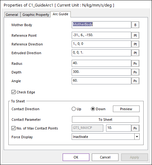
Select Apply.
As before, ensure that the contact direction is pointing the right way. It should appear as shown at below.
Click OK.
9.9.2.7.3. To create the inner linear guide:
Select the Linear Guide function from the Guide group under the MTT3D tab in the ribbon.
In the Input Window Toolbar, enter a start point of -20.660, 43.909.
In the Input Window Toolbar, enter an end point of -12.000, 38.909.
9.9.2.7.4. To create the outer linear guide:
Select the Linear Guide function from the Guide group under the MTT3D tab in the ribbon.
In the Input Window Toolbar, enter a start point of -11.000, 40.641.
In the Input Window Toolbar, enter an end point of -19.660, 45.641.
The model should now look as shown below.
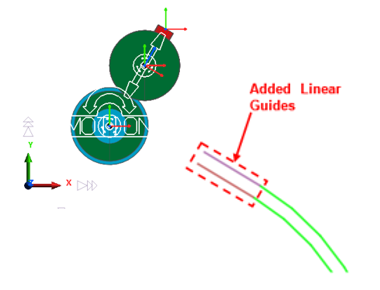
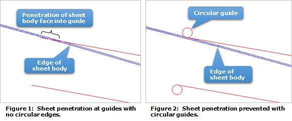
You now need to create small circular guides at the edges of the existing guides. It is always a good practice to do this in order to prevent penetration of the edges of the guides into the faces of the sheet bodies. The reason this is necessary is because the arc and linear guides contact only the edges of the individual sheet bodies, while the circular guides contact both the faces and the edges of the sheet bodies.
9.9.2.7.5. To create the circular guides:
Select the Circular Guide function from the Guide group under the MTT3D tab in the ribbon.
In the Modeling Window, select the left end of the outer linear guide you just created (GuideLinear2), as shown at below.
In the Modeling Window, move the mouse pointer above the guide such that the OrthoDirection arrow points upwards, as shown at below, and click.
In the Input Window Toolbar, enter a radius of 0.2.
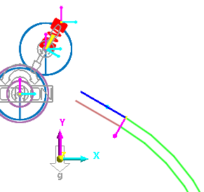
Repeat the steps above for the three other guides as shown below.
9.9.2.7.6. To create the printer tray:
Create three more linear guides, using the following start and end points.
Start Point
End Point
GuideLinear3
-351, 6
-51, 6
GuideLinear4
-351, 26
-351, 6
GuideLinear5
-51, 6
-51, 26
Open the Properties dialog for GuideLinear5, the guide on the right side of the tray.
To the right of Contact Parameter, select the To Sheet button.
Uncheck the boxes next to Stiffness and Maximum Damping.
Make the following settings.
Stiffness: 1.2
Maximum Damping: 1.2e-4
Note
The stiffness of the contact for GuideLinear5 should be increased to prevent contact penetration of the sheet edge into the guide at the end of the simulation. This can occur because after the sheet lands in the tray, it slides down until it hits GuideLinear5. Only the edge of the sheet contacts GuideLinear5, leaving less sheet bodies to react to the impact, and also the sheet’s direction of travel is exactly normal to the guide. Both these conditions make this guide more susceptible to being penetrated by the sheet. Another setting, the Maximum Time Step of the simulation, will also be adjusted later to prevent the same event.
Click Close.
Click OK.
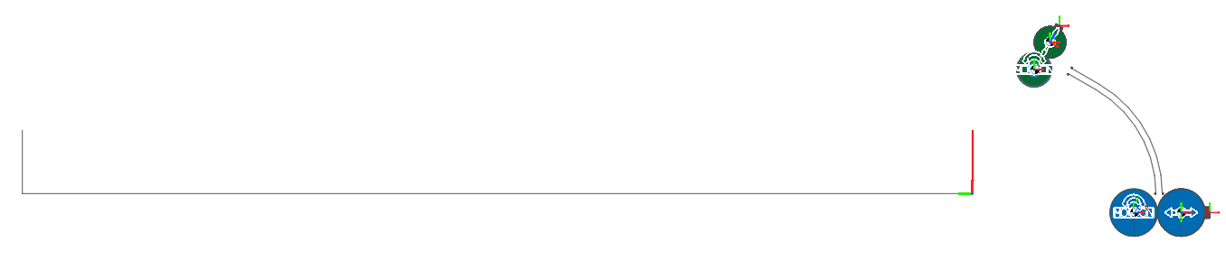
The model should now appear as shown below, with the tray flat. You will next rotate the tray about a reference marker at the right corner of the tray so that it is sloped.
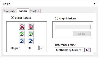
9.9.2.7.7. To rotate the paper tray:
Select the Marker function from the Marker and Body group under the Professional tab in the ribbon.
In the Modeling Window, click anywhere in the background to associate the Marker with the MotherBody.
In the Input Window Toolbar, enter the coordinates -51, 6. You will see a new marker at the right corner of the paper tray.
Using the Ctrl key, select the three guides that make up the tray.
From Advanced Toolbar, select the Basic Object Control tool.
Select the Rotate page.
Enter 15 degrees for the angle.
Under Reference Frame, click M.
From the Modeling Window, select MotherBody.Marker8 (the marker you just created).
Click the Clockwise about Z button.
Close the Basic Object Control dialog.
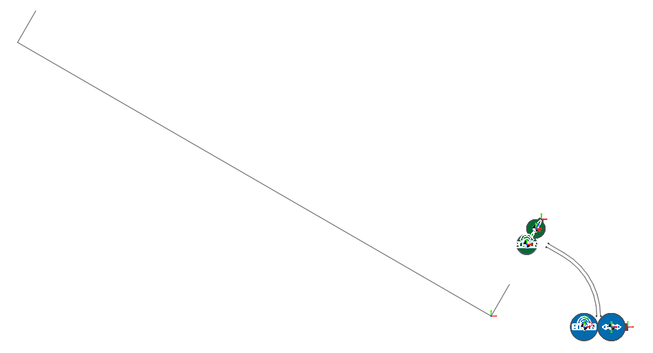
The tray should now appear as shown below.
9.9.2.8. Creating the Sheet
You will now create the sheet and position the lower rollers around it.
9.9.2.8.1. To create the sheet:
Select the Shell Sheet function from the Sheet group under the MTT3D tab in the ribbon.
In the Input Window Toolbar, enter a start point of 7.525, 5.
In the Input Window Toolbar, enter a direction of 0, -1.
The SheetShell dialog should appear as shown below. If it does not, move the mouse pointer into the Modeling Window and it should appear.
Make the following settings in the SheetShell dialog shown at below.
Thickness: 0.05
Total Length (Longitudinal): 150
Number of Node (Longitudinal): 41
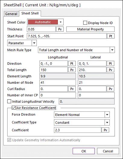
Select the checkbox next to Air Resistance Coefficient.
Click OK.
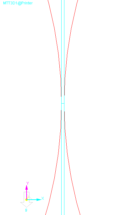
The sheet has been created, but if you were to zoom into the sheet where it is between the rollers, you would see that it is penetrating the rollers and that the rollers have not been separated enough to accommodate the sheet, as shown at below. Therefore, the next step will be to align the sheet and rollers in a reasonable starting position.
9.9.2.8.2. To align the sheet within the rollers:
Select the Align Sheet function from the Roller group under the MTT3D tab in the ribbons.
In the Working Window, select SheetShell1, the sheet group you just created.
In the Working Window, select MovableRollerGroup1, the roller to the right of the sheet.
- Select OK when asked whether to align the sheet or not.The sheet and movable roller should now have been moved into position as shown at below.
Save the model.
9.9.3. Running a Simulation
9.9.3.1. Task Objective
In this chapter, you will start a simulation and monitor its progress. Later, to save time, you will open a model identical to the one you created which will already have results for a complete simulation loaded and observe the results.
9.9.3.2. Estimated Time to Complete
10 minutes
9.9.3.3. Running a Simulation
You will now start a simulation and monitor its progress.
9.9.3.3.1. To run the simulation:
Select the Dynamic / Kinematic Analysis function from the Simulation Type group under the Analysis tab in the ribbon.
Make the following settings, as shown at below.
End Time: 1
Step: 200
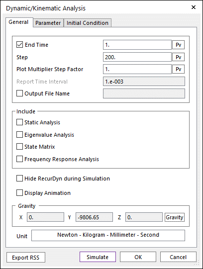
Select the Parameter page.
Change Maximum Time Step to 1e-3.
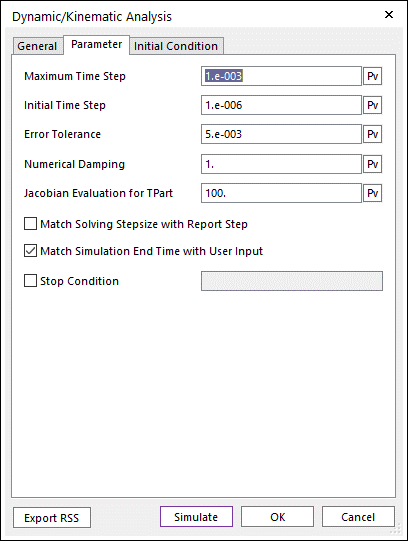
Note
For this simulation, the maximum time step should be reduced to prevent penetration of the sheet edge into GuideLinear5 on the right side of the tray. This can occur because near the end of the simulation, when the sheet is simply sliding down the tray, the integration time step can become too large since the motion of the sheet is very simple.The sheet continues to slide until it hits the bump stop at the right side of the tray, GuideLinear5. If the time step is too large at this point, the simulation can jump too quickly from one state in which the sheet edge is on one side of the bump stop to another in which the sheet edge is on the other side, without registering the sheet-to-guide contact correctly in between.Click Simulate and allow the simulation to run for several minutes.
While the simulation is running, you can stop it and play the animation of the completed results to monitor its progress.
9.9.3.3.2. To monitor the simulation:
From Simulation Toolbar, click the Pause Simulation tool. The animation controls should now become active.
From Simulation Toolbar, click the Play tool. You can use any of the animation controls to view the results as if the simulation were complete.
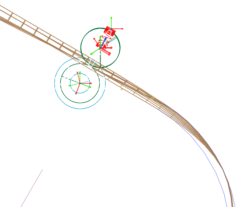
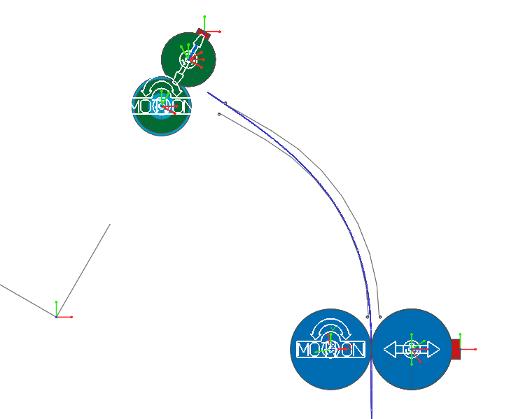
With the simulation at about 20% complete, you should see that the sheet has progressed through the guides and has started entering the corrugating roller pair, as shown below. At this point, the simulation will run slower due to the higher amount of sheet deformation and contact which will occur during its corrugation.
From Simulation Toolbar, click the Resume Simulation tool, in order to continue the simulation.
9.9.3.4. Viewing the Completed Simulation Results
If you have a powerful desktop computer with multiple processing cores, the simulation can take less than one minute to complete. However, due to the limited time you may have to complete this tutorial, you will now open an identical model which already has results from a complete simulation loaded.
9.9.3.4.1. To open the completed model:
From Simulation Toolbar, click the Stop simulation tool.
From the File menu, select the Open function.
Navigate to the tutorial subdirectory labeled Printer_complete.
Select the file Printer_complete.rdyn.
Select Open.
Enter the MTT3D1 subsystem.
In the Database Window, right-click on Subsystems > MTT3D1, and select Edit.
OR
In the Modeling Window, double-click on any geometric entity of the MTT3D1 subsystem.
If the animation controls are grayed out, you will need to simulate it.
9.9.3.4.2. To view the stress contour plot:
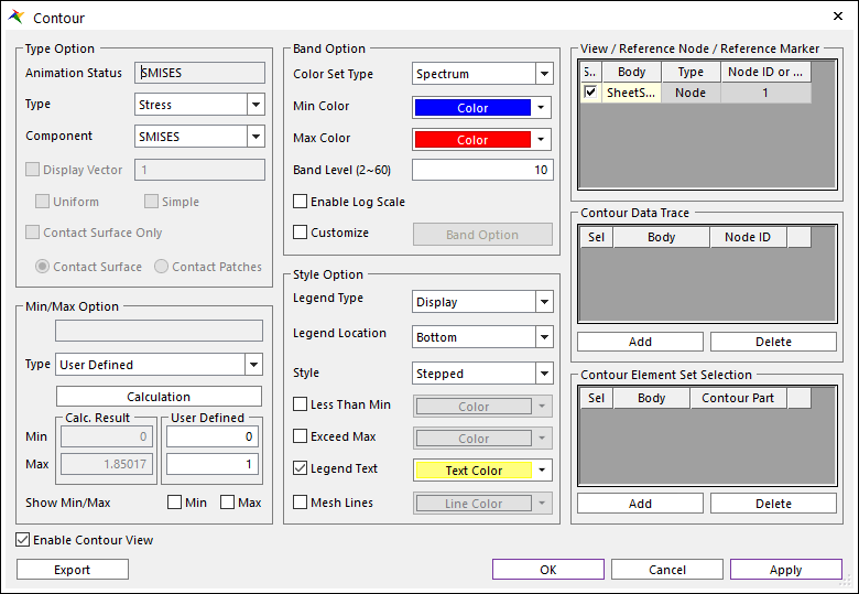
Select the Contour function in the Contour group under the MTT3D tab.
In the Contour Option section, from the Type dropdown menu, select Stress.
Select SMISES from the displayed list of data types.
In the Min/Max Option section, from the Type dropdown, select User Defined.
Enter a Max value of 1.
In the Style Option section, from the Style dropdown, select Smooth.
Also set the Text Color to be black.
Click OK.
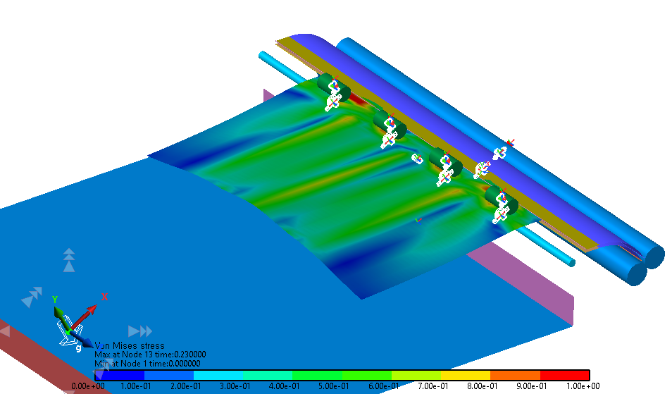
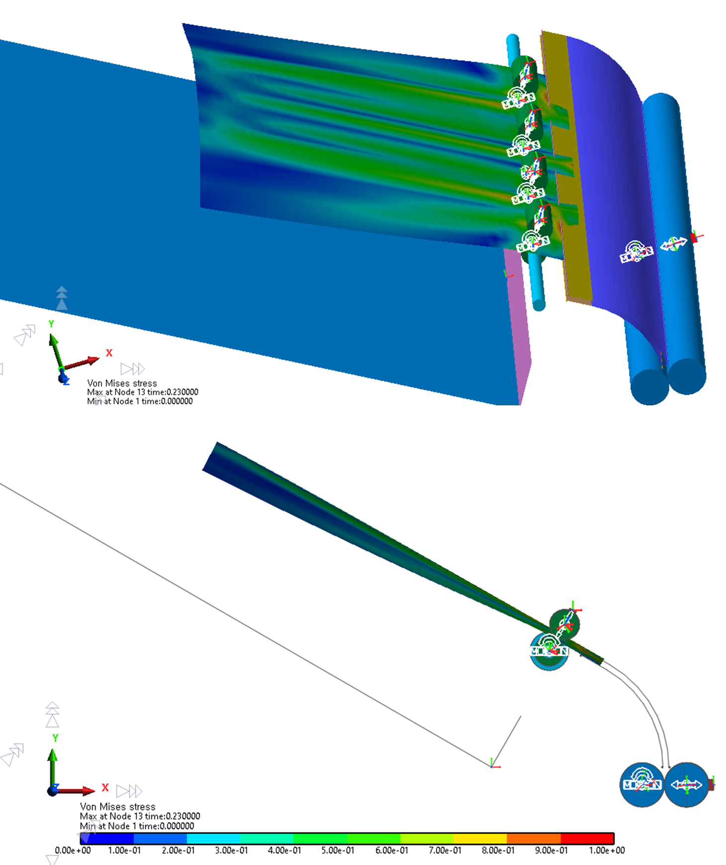
The areas of high stress indicate where the corrugation is occurring as the sheet proceeds out of the rollers. In the second frame below, you can see when the corrugation dissipates due the increasing mass of the sheet away from the rollers, before the sheet is released.
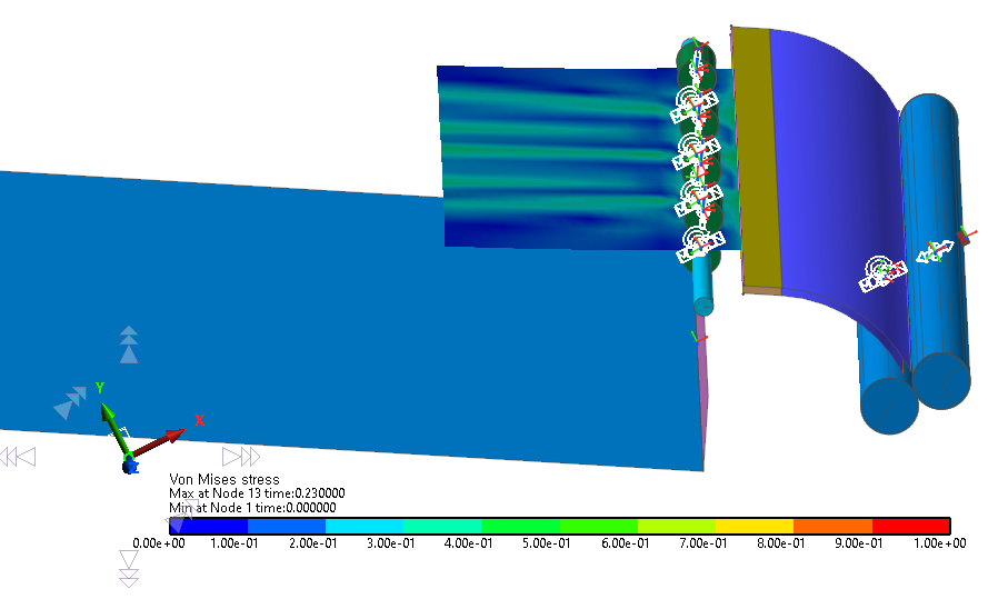
The simulation shows that the design does not maintain the corrugation in the sheet for as long of a time as intended. In the next chapter, you will modify the design to increase the corrugation effect.
9.9.4. Modifying the Design
9.9.4.1. Task Objective
In this chapter, you will modify the design of the corrugation roller to increase the corrugation, in an effort to keep the sheet straight until it exits the printer. You will then import simulation results for the modified design and evaluate its performance.
9.9.4.2. Estimated Time to Complete
10 minutes
9.9.4.3. Modifying the Design
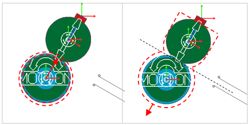
In order to increase the corrugation of the paper, the radius of the corrugating rollers will be increased. After that, all the upper rollers will be repositioned such that they remain aligned with the centerline of the linear guides, as shown below.
9.9.4.3.1. To increase the radius of the corrugating rollers:
Return to your model.
Open the Properties dialog of FixedRollerGroup3, the corrugating roller.
Click Multiple Roller Info..
Change the Radius values to 6.5, as shown at below.

Click Close.
Click OK.
9.9.4.3.2. To realign the upper rollers:
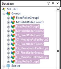
In the Database Window, use the Shift key to select all the items under Groups except for FixedRollerGroup1 and MovableRollerGroup1.
Select FixedRollerGroup2.
Hold down the Shift key.
Select FixedRollerGroup3.
From Advanced Toolbar, select the Basic Object Control tool.
Enter an Offset Value of 0.5.
Under Reference Frame, click M.
In the Working Window, select a marker which is aligned with the axes of the springs, as shown at below.
Click -Z, or whichever button will move the rollers down and to the left.
Close the Basic Object Control dialog.
Save the model under a different name, such as Printer_update.rdyn.
9.9.4.4. Evaluating the Design Change
The revised model is ready to simulate, but as before, you can open an identical model with previously completed simulation results, to save time.
9.9.4.4.1. To open the previously completed model:
Open the file Printer_update.rdyn, located again in the Printer_complete tutorial subdirectory.
Enter the MTT3D1 subsystem.
Simulate the model.
Enable the contour plots as done before.
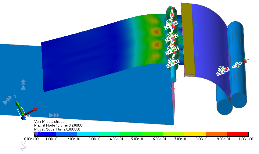
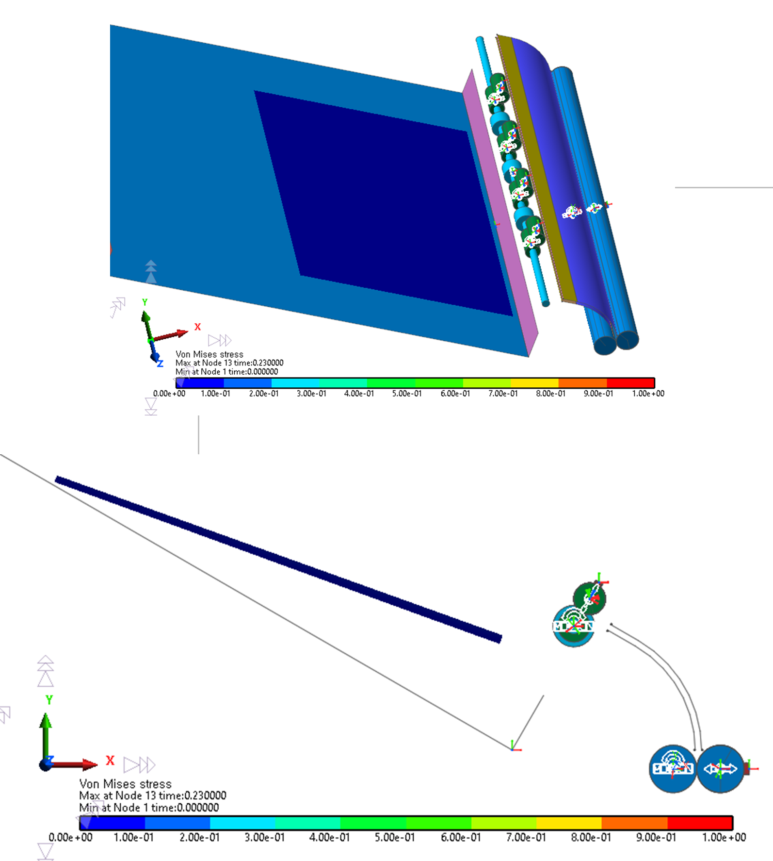
The results should now show an increased amount of corrugation, enabling the sheet to successfully remain straight until exiting the printer, as shown in the following figures.
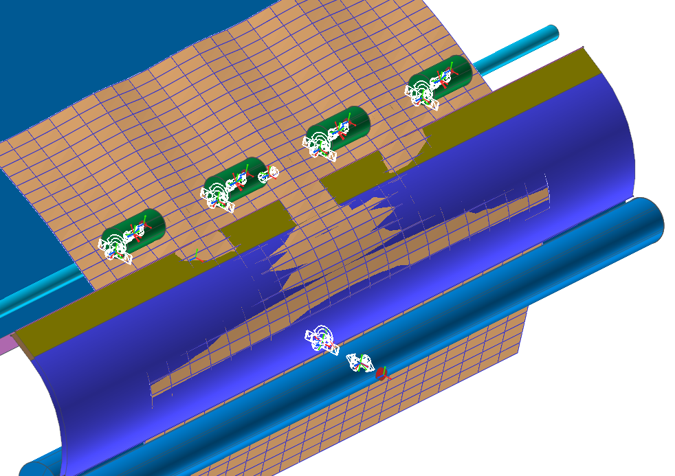
Note
In the modified model, you may notice some penetration of the sheet into the outer arc guide, as shown below.
Although this may appear to be a lot of penetration, it actually is not excessive. If viewed from the side, as shown below, you can see that the sheet is staying within the boundaries of the guides and the penetration is only on the order of 0.1 mm.