15.2.1. Calculation
The user can set parameter and compute the ERP.
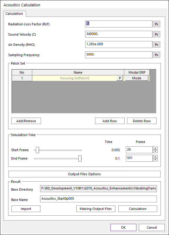
Figure 15.2 Calculation dialog box
Radiation Loss Factor (RLF): The default is 1.0.
Sound Velocity (C): The default is 340,000 mm/s.
Air Density (RHO): The default is 1.293e-9 kg/mm^3.
Sampling Frequency: The default is 100 Hz. The Sampling Frequency is used for the scope data. If the Sampling Frequency is used 1000 Hz, then the sampling time is set with 1.0/1000=0.001 s. Therefore, the computed time interval is defined as the 0.001s for the scope data.
Patch Set: Selects some patch sets any flexible (FFlex and/or RFlex) bodies.
Add/Remove: Adds and removes some patch sets.
Add Row: Adds a row for adding a patch set.
Delete Row: Deletes a row for remove a patch set.
Modal ERP: Accesses the Mode Selection dialog box as shown in the below figure. If the selected Patch Set belongs to the RFlex, the user can select modes to calculate a Modal ERP. The selected modes applies equally to all Patch Sets that belong to the same RFlex body
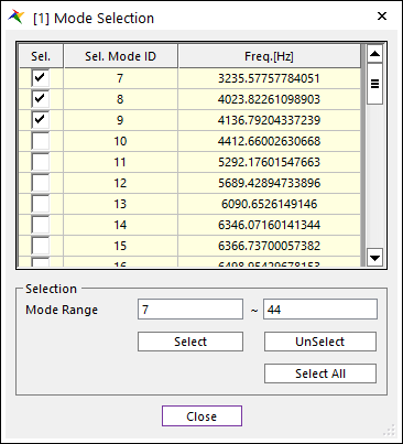
Figure 15.3 Mode Selection dialog box
Simulation Time: Selects number of animation frames.
Start Frame and End Frame: Sets start animation frame and end animation frame with a slider control.
Time: Shows simulation time each selected the Start Frame and End Frame.
Frame: Sets frame number. (A natural number is available.)
Output Files Options : Accesses the Output Files dialog box as shown in the below figure. The user can select data precision of *.ARD file and *.AMMX file(Single/Double). And the user can use option to delete *.ERP file after making output files.
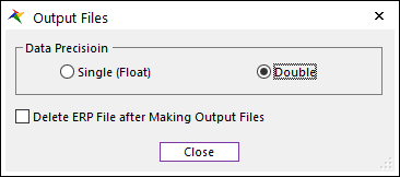
Figure 15.4 Output Files dialog box
Note
After using Delete ERP File after Making Output Files option, the Making Output Files function cannot be used.
Base Directory: Shows the base directory which has animation data and target directory for generating results files. Acoustics toolkit generates following files.
ACS file: has scope data (raw data).
ERP file: has ERP data (raw data).
ARD file: has a ERP contour data on a flexible body.
AMMX file: has a Min. and Max. ERP data for contour on a flexible body.
The Acoustics result files should exist on the base direction.
Base Name: Sets result name. The Base Name is a model name.
Import: If previous calculated Acoustics result exists, then the Acoustics Result List dialog shows available list. The user selects a previous calculated Acoustics result. Note that the user should have previously selected the Patch-Set used at the time of the calculation of the selected result.
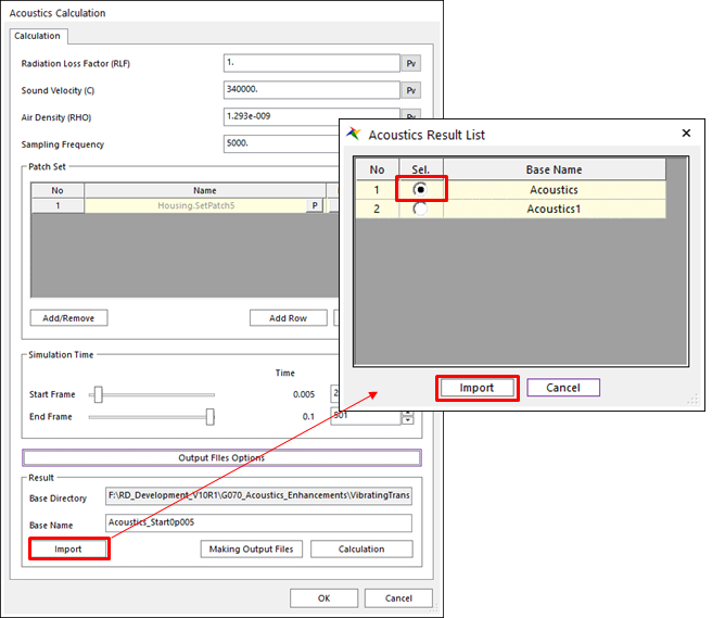
Figure 15.5 Acoustics Result List dialog box
Making Output Files: Calculates *.ARD and *.AMMX Files by using *.ERP File.
Calculation: Calculates Acoustics results. And the calculated result is imported. If the base name exists in the base directory, then the results are changed with latest parameters.