20.6.9.1. PMDC
The PMDC machine block implements a permanent magnet excited DC motor.
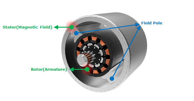
Figure 20.136 PMDC Motor
Dialog Box
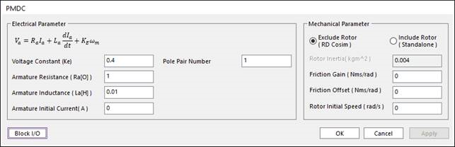
Figure 20.137 PMDC dialog box
Parameter Name |
Signal |
Description |
Voltage Constant |
\(K_e\) |
Back electromotive force (BEMF) constant. In DC Motor it is same as Torque constant. You can find the value of Voltage Constant or the Torque Constant in the datasheet. |
Pole Pair Number |
The number of pole pairs. It means how many pairs of Field Pole there are. |
|
Armature Resistance |
\(R_a\) |
The armature resistance between the armature terminal A+ and A-. You can find the value of Armature Resistance in the datasheet. [Ohms] |
Armature Inductance |
\(L_a\) |
The armature inductance between the armature terminal A+ and A-. You can find the value of Armature Inductance in the datasheet. [H] |
Armature Initial Current |
\(A\) |
Initial value of armature current. Set this value to ‘0’ if you don`t know it. |
Parameter Name |
Signal |
Description |
Exclude Rotor/Include Rotor |
Select the type of Motor between Exclude Rotor and Include Rotor. The more detail explanation of two types is in the Equation of PMDC. |
|
Rotor Inertia |
\(J\) |
Inertia of rotor. This parameter don`t need on the Rotor Speed Type. You can find the inertia of rotor in the datasheet. [kg*m^2] |
Friction Gain |
\(B\) |
Viscous friction gain between motor and load. When you apply the friction between the motor and the load in your dynamic model, you have to set this value to ‘0’. [Nms] |
Friction Offset |
\(T_f\) |
Viscous friction Offset between motor and load (\(B\omega+ offset\)). When you apply the friction between the motor and the load in your dynamic model, you have to set this value to ‘0’. [Nm] |
Rotor Initial Speed |
\(\omega\) |
Initial value of rotor speed. Set this value to ‘0’ if you don`t know it. [rad/s] |
20.6.9.1.1. Input and Output of PMDC
Exclude Rotor (RD Cosim) Type
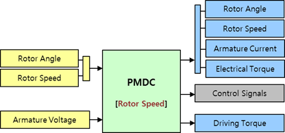
Figure 20.138 Input Port and Output Port of Rotor Speed Type
Port |
Input Signal |
Description |
|
1st Port |
Rotor Angle |
\(\theta\) |
The Rotor Angle. [rad] |
Rotor Speed |
\(\omega\) |
The Rotor Angular Speed. This value is a differential of Rotor Angl. [rad/s] |
|
2nd Port |
Armature Voltage |
\(V_q\) |
The Armature Voltage. [V] |
Port |
Output Signal |
Description |
|
1st Port |
Rotor Angle |
\(\theta\) |
The Rotor Angle. [rad] |
Rotor Speed |
\(\omega\) |
The Rotor Angular Speed. [rad/s] |
|
Armature Current |
\(I_a\) |
The Armature Current. [A] |
|
Electrical Torque |
\(T_e\) |
The Generated electrical torque. [N.m] |
|
2nd Port |
Control Signals |
This signal is used when you control the motor use the PMDC Drive block. When you use the PMDC Machine block, this port does not export any signal. |
|
3rd Port |
Driving Torque |
\(T_d\) |
The driving torque \({{T}_{d}}\) subtracts the viscous friction of rotor from the electrical torque \({{T}_{e}}\). The more detail explanation of this is in the Rotor Speed part of the Equation of PMDC. [N.m] |
Example
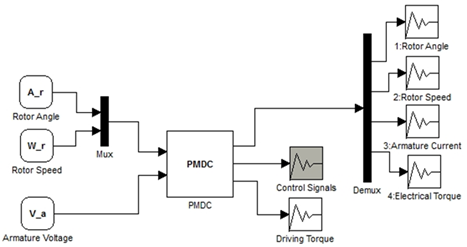
Figure 20.139 Example of Rotor Speed Type
Include Rotor (Standalone) Type
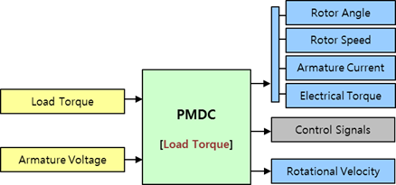
Figure 20.140 Input Port and Output Port of Load Torque Type
Port |
Input Signal |
Description |
|
1st Port |
Load Torque |
\(T_L\) |
The Load Torque. This value is used to calculate the Driving Torque in the Load Torque Type. [N] |
2nd Port |
Armature Voltage |
\(V_a\) |
The Armature Voltage. [V] |
Port |
Output Signal |
Description |
|
1st Port |
Rotor Angle |
\(\theta\) |
The Rotor Angle. [rad] |
Rotor Speed |
\(\omega\) |
The Rotor Angular Speed. [rad/s] |
|
Armature Current |
\(I_a\) |
The Armature Current. [A] |
|
Electrical Torque |
\(T_e\) |
The Generated electrical torque. [N.m] |
|
2nd Port |
Control Signals |
This signal is used when you control the motor use the PMDC Driver block. When you use the PMDC Machine block, this port does not export any signal. |
|
3rd Port |
Rotational Velocity |
Rotor Rotational Velocity. [rad/s] |
Example
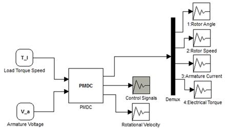
Figure 20.141 Example of Load Torque Type
20.6.9.1.2. Equation of PMDC
Electrical Part
The voltage equations of PMDC are as follows.
\({{V}_{a}}={{R}_{a}}{{I}_{a}}+{{L}_{a}}\frac{d{{I}_{a}}}{dt}+E\)
- where,
- \({{V}_{a}}\) is the input armature voltage.\({{R}_{a}}\) is the armature resistance.\({{L}_{a}}\) is the armature inductance.\({{I}_{a}}\) is the armature current.\(E\) is the back electromotive force.
The armature winding is connected to the outside terminal. This block is very similar to a shunt connected DC motor. A back electromotive force (BEMF) by magnet, which is generated between the armature terminals, is proportional to the machine speed.
\(E={{K}_{E}}{{\omega }_{m}}\)
- where,
- \({{K}_{E}}\) is the voltage (BEMF) constant\({{\omega }_{m}}\) is the mechanical angular speed.
The electrical torque, which is developed by PMDC motor, is proportional to the armature current \({{I}_{a}}\).
\({{T}_{e}}={{K}_{E}}{{I}_{a}}={{K}_{T}}{{I}_{a}}\)
The torque constant \({{K}_{T}}\) is equal to the voltage (BEMF) constant \({{K}_{E}}\).
When the machine is in generator mode, the sign of torque is positive. In motor mode, the sign of torque is negative.
Mechanical Part
Exclude Rotor
The driving torque \({{T}_{d}}\) subtracts the viscous friction of rotor from the electrical torque \({{T}_{e}}\).
\({{T}_{d}}={{T}_{e}}-sign({{\omega }_{m}})(B\left| {{\omega }_{m}} \right|+{{T}_{f}})\)
- where,
- \(B\) is the viscous friction gain.\({{T}_{f}}\) is the viscous friction offset.
Include Rotor
The mechanical dynamics of the rotor is governed by the equation.
\({{T}_{e}}=J\frac{d{{\omega }_{m}}}{dt}+sign({{\omega }_{m}})(B\left| {{\omega }_{m}} \right|+{{T}_{f}})+{{T}_{L}}\)
- where,
- \(J\) is the inertia of rotor.\(B\) is the viscous friction gain.\({{T}_{f}}\) is the viscous friction offset.\({{T}_{L}}\) is the load torque.