39.1.2.4. Bearing Section Setting
Profile
Profile defines an offset data in angle and height coordinate. User can apply arbitrary bearing shape to EHD analysis by setting this offset table data.
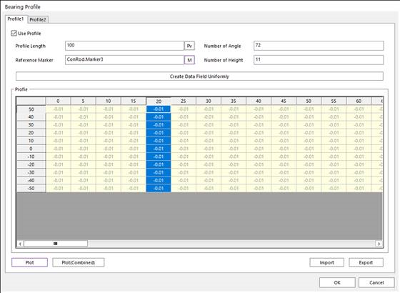
Figure 39.17 Bearing Profile dialog box
Use Profile: On/Off check option.
Profile Length (L): Defines profile height length.
Number of Angle: Defines number of angles of profile data in angle direction. If user click ‘Create Data Field Uniformly’, profile coordinate in angle direction is generated automatically at interval where 360 degrees are divided by the number.
Number of Height: Defines number of heights of profile data in height direction. If user click ‘Create Data Field Uniformly’, profile coordinate in height direction is generated automatically at interval where profile length (L) is divided by the (number-1). The height range is from –L/2 to L/2.
Reference Marker: Select reference marker to define profile data. Height direction of profile is the same as Z axis of the marker and angle direction is the same as rotation direction from X to Y axis.
Create Data Field Uniformly: Make profile data according to defined height length (L), number of angle and number of heights automatically. Profile coordinate in height direction is generated at interval where profile length is divided by the (number of height - 1). The height range is from –L/2 to L/2. Profile coordinate in angle direction is generated at interval where 360 degrees are divided by the number of angles. Default value for offset is ‘0’
Import & Export: User can make profile data chart of *.csv file format by exporting profile chart in dialog. Additionally, user can also import the *.csv file and modify current profile data in dialog. Profile data can be modified in the only *.csv file.
Plot: Display curve plot for the profile data. User can click angle or height coordinate. And then, if the user clicks Plot, curve plot for profile is displayed.
Plot (Combined): Display curve plot for the total profile data in which profile1 and profile2 are combined.
Film Thickness
Film Thickness sets user-defined thickness distribution data in axial direction. The method of user defined thickness data is making one dimensional profile data similar to offset profile. User can set the oil to a sufficient and deficient condition with this data.
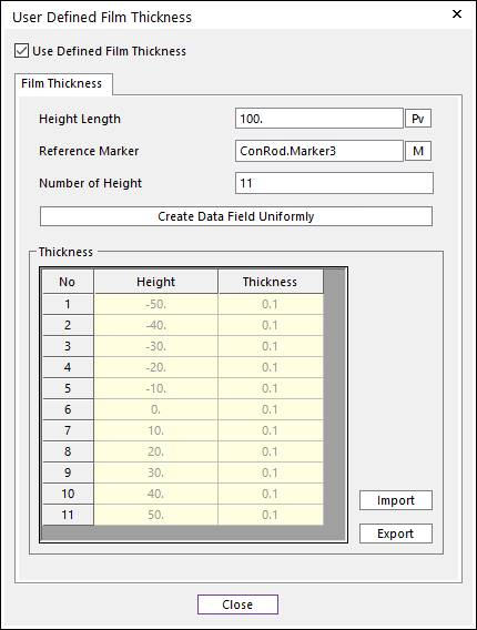
Figure 39.18 User Defined Film Thickness
Height Length: Defines profile height length for user defined thickness.
Reference Marker: Select reference marker to define profile data. Height direction of profile is the same as Z axis of the marker.
Number of Height: Defines number of heights of profile data in height direction.
Create Data Field Uniformly: Make profile data for user defined thickness according to defined height length and number of heights. Profile coordinate in height direction is generated automatically at interval where height length is divided by the (number-1). The height range is from –L/2 to L/2. Default value for thickness is the same as initial clearance between piston and cylinder.
Import & Export: User can make profile data chart by *.csv file format by exporting profile chart for used defined thickness in dialog. Additionally, user can also import the *.csv file and modify current profile data in dialog. This is one dimensional array unlike offset profile.
Step to define Film Thickness
Set Reference Marker and Height. The reference marker must belong to the base body.
- Set Thickness Profile.The EHD pressure value appears as 0 in the deficient condition (Initial Clearance > Film Thickness)In the opposite case (Initial Clearance <= Film Thickness), the EHD pressure value is calculated normally.