5.5.2.1. FRA Excitation Loads
User can set a FRA Input Channel and FRA Output Channel.
FRA Input is provided as follows.
Force/Torque: FX, FY, FZ, TX, TY, and TZ.
Displacement: DX, DY, DZ, RX(Roll), RY(Pitch), and RZ(Yaw).
Velocity: VX, VY, VZ, WX, WY, and WZ.
Acceleration: ACCX, ACCY, ACCZ, WDTX, WDTY, and WDTZ.
FRA Output is provided as follows.
Displacement: TX, TY, TZ, RX(Roll), RY(Pitch), RZ(Yaw), and TM.
Velocity: VX, VY, VZ, WX, WY, WZ, VM, and WM.
Acceleration: ACCX, ACCY, ACCZ, WDTX, WDTY, WDTZ, ACCM, and WDTM.
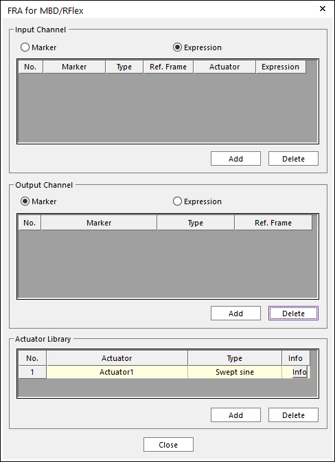
Figure 5.30 FRA for MBD/RFlex dialog box
Input Channel
There are two types as Marker and Expression.
Marker type
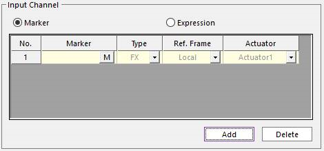
Figure 5.31 Marker type of the FRA Input
Marker: User can select a marker.
Type: FX, FY, FZ, TX, TY, TZ, DX, DY, DZ, RX(Roll), RY(Pitch), RZ(Yaw), VX, VY, VZ, WX, WY, WZ, ACCX, ACCY, ACCZ, WDTX, WDTY, and WDTZ.
Reference Frame: There are two options as Local and Global. Local reference frame means that the X, Y, and Z axis of input force or torque is defined as the selected marker. Global reference frame means that the X, Y, and Z axis of input force or torque is defined as Ground.InertiaMarker.
Actuator: User can select an actuator in the actuator library.
Expression type
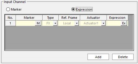
Figure 5.32 Expression type of the FRA Input
Marker, Type, Ref. Frame, and Actuator: Refer to Marker type of FRA input.
Expression: User can set of magnitude value of the FRA input force/torque with an expression. This value can be set in Expression type of FRA input.
Output Channel
Marker type
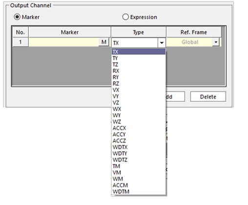
Figure 5.33 Marker type of the FRA Input
Marker: User can select a marker.
Type: TX, TY, TZ, RX, RY, RZ, VX, VY, VZ, WX, WY, WZ, ACCX, ACCY, ACCZ, WDTX, WDTY, WDTZ, TM, VM, WM, ACCM, and WDTM.
Ref. Frame: There are two options as Local and Global. Local reference frame means that the X, Y, and Z axis of input force or torque is defined as the selected marker. Global reference frame means that the X, Y, and Z axis of input force or torque is defined as the inertia reference frame.
Expression
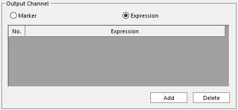
Figure 5.34 Expression type of the FRA Output
User can freely make an FRA output channel with the expressions. For more information about Expression, click here.
Actuator Library
An actuator is created by default named Actuator1.
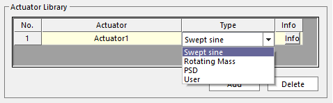
Figure 5.35 Actuator Library
Actuator: User can set and modify the name.
Type: There are 4 type named Swept Sine, Rotating Mass, PSD, User.
Info: User can set and modify the parameters of the selected actuator. These parameters influence to the Frequency Response with Actuator of the FRA Plot data.
Swept Sine is consistent for two parameters as magnitude and phase angle. In order to set the parameters, click Info.
Force Magnitude: Is a dimensionless magnitude factor for the actuator input. This factor is multiplied to the Input channel.
Phase Angle: Is a shift angle for the actuator input. This angle shifts the phase of Input channel. The unit is a degree.
For example, if the input is \(\sin (\omega t)\), Force Magnitude is \(\alpha\), and Phase angle is \(\phi\), then the result response (\(y\)) is evaluated as \(y=Hu_{actuator}\). Here, \(u_{actuator}=\alpha \sin (\omega t+\phi )\).
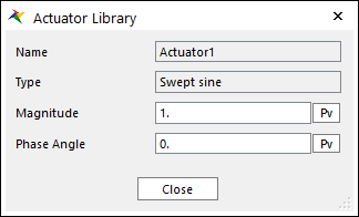
Figure 5.36 Actuator Library: Swept Sine
Rotating Mass is consistent for two parameters as magnitude and phase angle. In order to set the parameters, click Info.
Force Type: Is a dimensionless magnitude factor for the actuator input which is represented by two actuators. This factor is multiplied to the Input channel. The Leading and Lagging actuators are represented:
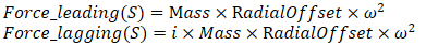
Moment Type: Is a shift angle for the actuator input. This angle shifts the phase of Input channel. The unit is a degree.

Each leaing type and lagging type actuators could be applied on the same input channel. The first actuator should be defined as a Leading actuator and the second as the Lagging actuator.
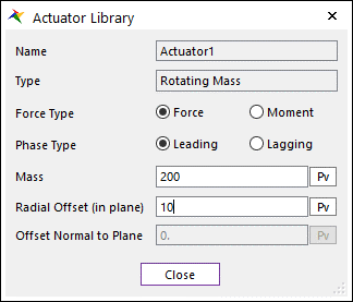
Figure 5.37 Actuator Library: Rotating Mass
PSD(Power Spectral Density) is consistent for two parameters as magnitude and phase angle. In order to set the parameters, click Info.
Force Magnitude: Is a dimensionless magnitude factor for the actuator input which is defined by using a spline function. This factor is multiplied to the Input channel.
Phase Angle: Is a shift angle for the actuator input. This angle shifts the phase of Input channel. The unit is a degree.
For example, if the input is \(\sin (\omega t)\), Force Magnitude is \(\alpha\), and Phase angle is \(\phi\), then the result response (\(y\)) is evaluated as \(y=Hu_{actuator}\). Here, \(u_{actuator}=\alpha \sin (\omega t+\phi )\).
( PSD type actuator cannot use with the vibration actuators of the other type.)
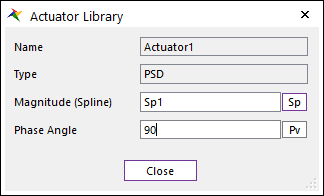
Figure 5.38 Actuator Library: PSD
User is consistent for two parameters as magnitude and phase angle. In order to set the parameters, click Info.
Force Magnitude: Is a dimensionless magnitude factor for the actuator input which have a function using the variable “freq”. This factor is multiplied to the Input channel.
Phase Angle: Is a shift angle for the actuator input. This angle shifts the phase of Input channel. The unit is a degree.
For example, if the input is \(\sin (\omega t)\), Force Magnitude is \(\alpha\), and Phase angle is \(\phi\), then the result response (\(y\)) is evaluated as \(y=Hu_{actuator}\). Here, \(u_{actuator}=\alpha \sin (\omega t+\phi )\).
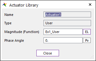
Figure 5.39 Actuator Library: User