29.5.2.2. Properties
The Shell Belt property page is shown in Figure 29.89. And its parameters are explained below. The user can modify properties for the shell belt such as geometry information, FFlex body characteristics, boundary condition, and output. The general pages such as General Page, Graphic Property Page, Origin and Orientation Page are same with general body.
FE Info (Refer to FEInfo. in FFlex)
Connecting Parameter (Refer to Connecting Parameter in FFlex)
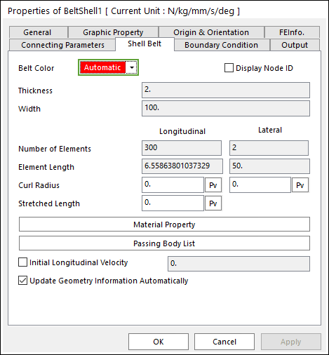
Figure 29.89 Shell Belt tab in the Properties of BeltShell dialog box
Belt Color: Changes the belt color.
Display Node ID: If this function is checked, the IDs of all nodes belong to the displaying belt.
Thickness: Enters the thickness of belt.
Width: Enters the width of belt.
Number of Elements: Enters the number of force elements to connect nodes.
Element Length: Enters the length of element.
Curl Radius: Defines the curve radius of belt along two directions.
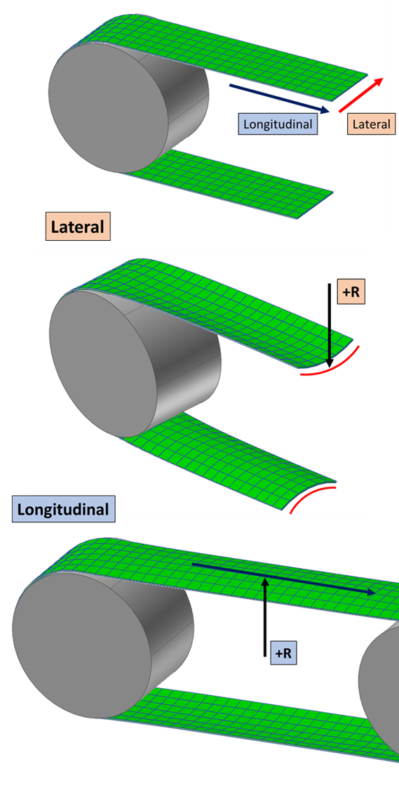
Figure 29.90 Belt curl radius in two directions
Stretched Length: Defines the stretched longitudinal length from the initial longitudinal length.
Initial longitudinal length = element longitudinal length-stretched length
Material Property: Allows you to access the dialog box defining the material property of belt. Refer to Material Property.
Passing Body List: Displays all geometries contacted belts.
Initial Velocity: Enters the initial velocity in the longitudinal direction of belt.
29.5.2.2.1. Material Property
The Material Property dialog box is shown clicking Material Property in the Shell Belt dialog box. The shell belt supports 3 types of material. Refer to Linear elastic. The parameters are explained below. The parameters are explained below.
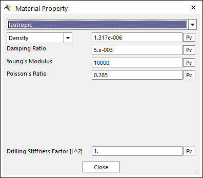
Figure 29.91 Material Property dialog box [Isotropic]
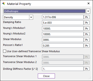
Figure 29.92 Material Property dialog box [Orthotropic]
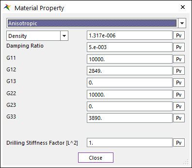
Figure 29.93 Material Property dialog box [Anisotropic]
Density or Total Mass: Allows you to choose the density or total mass of the belt.
Damping Ratio( \(\xi\) ): Defines the damping ratio. It has the:
Structural damping ratio of belt
Damping matrix of \({C}\)
They are computed from the following equation.
\({C} = \xi \cdot {K}\)
Drilling Stiffness factor: Defines the multiplier factor of drilling stiffness. If the drilling of shell element is too flexible, the shell element is changed stiffer for the only drilling stiffness by enlarging the factor.
Isotropic
Young’s Modulus and Poisson’s Ratio is set. In general, Shear Modulus is calculated from the Young’s Modulus and the Poisson’s Ratio in the isotropic material.
Young’s Modulus: Is the Young’s Modulus of belt.
Poisson’s Ratio: The shear modulus (G) is calculated.
Orthotropic
The orthotropic material is applied to the shell4.
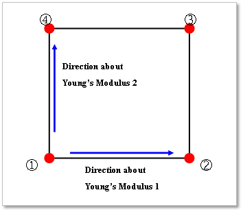
Young’s Modulus 1: Young’s Modulus of the orthotropic in the local direction by the local node 2 to the local node 1.
Young’s Modulus 2: Young’s Modulus of the orthotropic in the local direction by the local node 4 to the local node 1.
Shear Modulus (G): In-plane shear modulus.
Poisson’s Ratio 1 (v1): Note that \(\nu_1E_2=\nu_2E_1\)
Use User-defined Transverse Shear Modulus: Defines the transverse shear modulus. If this check option is disabled, shear correction factor is used to obtain the transverse shear modulus, which is a default value for original orthotropic material. If checked, user can set the transverse shear modulus.
Transverse Shear Modulus 1: Transverse shear modulus in direction 1 (G1z).
Transverse Shear Modulus 2: Transverse shear modulus in direction 2 (G2z).
Anisotropic
G11 to G33 represents the component of constitutive matrix in shell material.