30.2.4. Silent Sprocket
The chain converts rotational power to pulling power, or pulling power to rotational power, by engaging with the sprocket. In general, a chain system employs single sprocket consisted of teeth and the main body named sprocket hub. Exact sprocket tooth geometry must be defined. The sprocket tooth geometry data can be created, edited, exported or imported from a predefined data file.
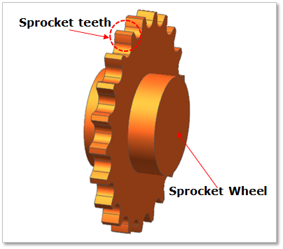
Figure 30.29 Silent Sprocket geometry
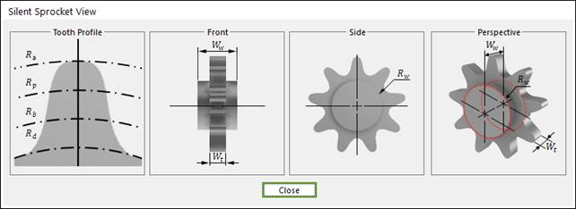
Figure 30.30 Silent Sprocket dimension information
Rw |
Sprocket Wheel Radius |
Wt |
Width of Teeth |
Ww |
Width between Wheels |
Rd |
Dedendum Circle Radius |
Rb |
Base Circle Radius |
Rp |
Pitch Circle Radius |
Ra |
Addendum Circle Radius |
30.2.4.1. Modeling Options
The user can create a sprocket as follows.
Point, WithDialog
Point: Selects a point to define the center of the sprocket.
WithDialog: Modifies the property for the sprocket. The sprocket is created with clicking OK.
30.2.4.2. Properties
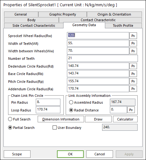
Figure 30.31 Silent Sprocket property page [Geometry Data page]
The Silent Sprocket property page is shown in Figure 30.31. The parameters are explained below. In order to understand the geometry, refer to Dimension Information.
Sprocket Wheel Radius(Rw): Enters the wheel radius of sprocket.
Width of Teeth(Wt): Enters the teeth width of sprocket.
Width between Wheels(Ww): Enter the wheel width of sprocket.
Number of Teeth: Enters the number of teeth.
Dedendum Circle Radius(Rd): Enters the dedendum circle radius of tooth profile.
Base Circle Radius(Rb): Enters the base circle radius of tooth profile.
Pitch Circle Radius(Rp): Enters the pitch circle radius of tooth profile.
Addendum Circle Radius(Ra): Enters the addendum circle radius of tooth profile.
Chain Link Pin Circle
The user can define easily relation of between sprockets and links using Pin Radius and Loop Radius.
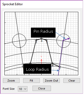
Figure 30.32 Sprocket Editor dialog box
Link Assembly Information
The gap between silent chain links and silent sprocket teeth can be controlled by Assembled Radius or Radial Distance.
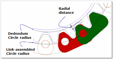
Figure 30.33 Silent Sprocket tooth profile
Full Search: All links are searched for contact.
Partial Search: Some links are searched for contact in some boundary. It is used to reduce total solving time.
User Boundary: In the case of Partial Search, the search boundary can be modified.
30.2.4.2.1. Tooth Profile
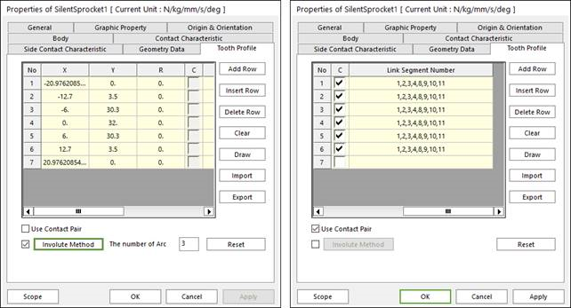
Figure 30.34 Silent Sprocket property page [Tooth Profile tab]
X,Y,R: Defines points and radius.
C, Link Segment Number: If Use Contact Pair option is checked, points for contact with links can be selected and node number of the link for contact can be modified.
Add Row: Adds a row to the end of the table.
Insert Row: Inserts a row where the cursor is and move the current and later rows down.
Delete Row: Deletes the row where the cursor is and move the later rows up.
Clear: Deletes all rows in the table.
Draw: All data must be defined with respect to the sprocket tooth marker. You can move points graphically by using the mouse directly.
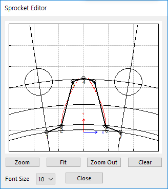
Figure 30.35 Sprocket Editor dialog box
Import: Imports the X, Y, and R data pairs from a CSV file or a MAT file or a text file. In the case of the text file, the usage of the comma, the tab, and the space can be the delimiter between the three columns in the file. And when using the Excel file, the user can select the Tab-delimited text file output option or the CSV (Comma-Separated Values) file output option to save the Excel file which can be imported.
Export: Exports the X, Y, and R data pairs to a CSV file or a MAT file or a text file.
Use Contact Pair: by dragging the scroll bar to the right side, a user can see hidden data (Link Segment Number) which contact with node number of a silent sprocket respectively.
Involute Method: If it is checked, the tooth profile can be defined as the involute curve.
The number of Arc: If Involute Method function is activated, the user can enter the number of arcs. The involute curve of gear tooth is represented by multiple arcs.
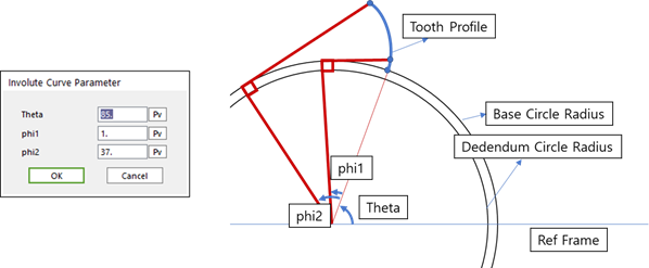
Figure 30.36 Input parameter & Outline of Involute formulation
Reset: In order to apply the modification of tooth, this button should be clicked.
Contact between a Silent Sprocket and a Silent link
The sprocket is in contacts with the chain link in the two parts.
The sprocket teeth surface - the roller of chain link
The outer side of virtual flange link - the outer side of chain outer link
Contact range is the addendum circle ranges(sprocket) plus pitch(link).
Note
If the CM of the link is included in the contact range, RecurDyn determines the contact between sprocket and link.
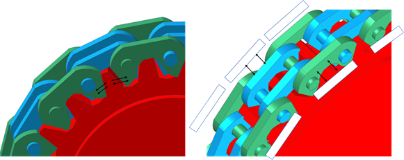
Figure 30.37 Contact between a sprocket and chain links
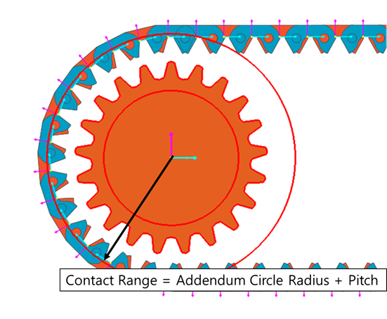
Figure 30.38 Contact Range