25.12.4. Tension Sensor
This sensor has a mother body, a center position, and a range. The figure is a sphere and the radius is same as range.
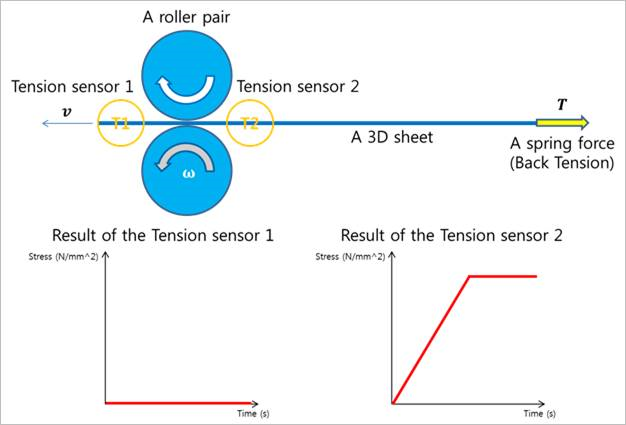
Figure 25.104 Tension Sensor
As shown in Figure 25.104, if a sheet body passes within the range of the sensor, the sensor output can be computed from the following equation.
\(\begin{aligned} & {{A}_{e}}\equiv \left[ \begin{matrix} f{}_{e} & {{g}_{e}} & {{h}_{e}} \\ \end{matrix} \right] \\ & {{A}_{t}}\equiv \left[ \begin{matrix} f{}_{t} & {{g}_{t}} & {{h}_{t}} \\ \end{matrix} \right] \\ & \left( \begin{aligned} & {{g}_{c}}={{g}_{e}} \\ & {{f}_{c}}={{g}_{c}}\times {{h}_{t}} \\ & {{h}_{c}}={{g}_{c}}\times {{f}_{c}} \\ \end{aligned} \right) \\ & {{A}_{c}}\equiv \left[ \begin{matrix} f{}_{c} & {{g}_{c}} & {{h}_{c}} \\ \end{matrix} \right] \\ & {{{{\sigma }'}}_{c}}={{A}_{c}}^{T}{{\sigma }_{c}}A{}_{c} \\ & {{{{\sigma }'}}_{c}}=\left[ \begin{matrix} {{{{\sigma }'}}_{xx}} & {{{{\sigma }'}}_{xy}} & {{{{\sigma }'}}_{xz}} \\ {{{{\sigma }'}}_{yx}} & {{{{\sigma }'}}_{yy}} & {{{{\sigma }'}}_{yz}} \\ {{{{\sigma }'}}_{zx}} & {{{{\sigma }'}}_{zy}} & {{{{\sigma }'}}_{zz}} \\ \end{matrix} \right] \\ & {{\sigma }_{o}}={{{{\sigma }'}}_{xx}} \\ \end{aligned}\)
- where,
- \({{\sigma }_{o}}\) is a stress value and the result of sensor.\({{{\sigma }'}_{c}}\) is the local stress tensor of the closest position of Element in the range of the sensor.\({{\sigma }_{c}}\) is the global stress tensor of the closet position of Element in the range of the sensor. In the case of shell element, \({{\sigma }_{c}}\) is a mid-stress acting on the neutral surface.\({{A}_{c}}\) is the reference frame of the output of the sensor. The x axis of \({{A}_{c}}\) is an expecting direction vector for acting a tension force.\({{A}_{t}}\) is the reference frame of the sensor. The z axis of \({{A}_{t}}\) is the normal direction vector of the tension sensor.\({{A}_{e}}\) is the reference frame of the closest position of Element in the range of the sensor. The y axis of the \({{A}_{e}}\)
25.12.4.1. Modeling Options
The user can create a tension sensor as follows.
Point, Distance
Point: Selects a point on a body to define the center of tension sensor.
Distance: Defines a range of region to measure output.
Body, Point, Distance
Body: Selects a body to define the parent body of tension sensor.
Point: Selects a point on a body to define the center of tension sensor.
Distance: Defines a range of region to measure output.
FixedRollerGroup, Direction, Distance, Distance
FixedRollerGroup, MovableRollerGroup, Distance, Distance
25.12.4.2. Properties
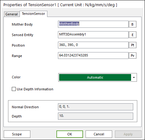
Figure 25.105 Tension Sensor property page
Mother Body: Defines the body on which the Tension Sensor is fixed.
Sensed Entity: Defines the sensed entity by the Tension Sensor of MTT3D.
If MTT3DAssembly is set, all sheets defined in the assembly become a sensing target.
If a sheet body is set, only the sheet becomes a sensing target.
Position: Defines the center point of Tension Sensor. The user can input this value as the Parametric Point.
Range: Defines the detecting range of Tension Sensor. The user can input this value as the Parametric Value.
Color: Allows selecting the graphic color of Tension Sensor.
Use Depth Information: Defines the sensing region by using the Normal Direction and Depth. The shape of sensing region is the cylinder type defined by the end point (Position), the radius (Range), the length (Depth), the lengthwise direction (Normal Direction) as shown in Figure 25.106. And the result tension is an averaging value of the nearest all sheet elements in some cylindrical segment centers like as Figure 25.108. The number of segments is defined a maximum number of nodes of the longitudinal or lateral nodes in the all including sheets of the MTT3D system.
If Depth information is not use, the shape of sensing region is the sphere type, which radius is same as range. And the tension is a calculated with a nearest sheet element.
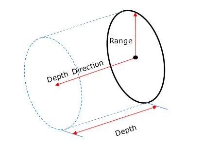
Figure 25.106 sensing region when the Use Depth Information is checked
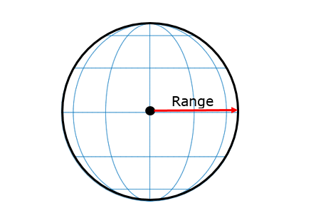
Figure 25.107 sensing region when the Use Depth Information is unchecked
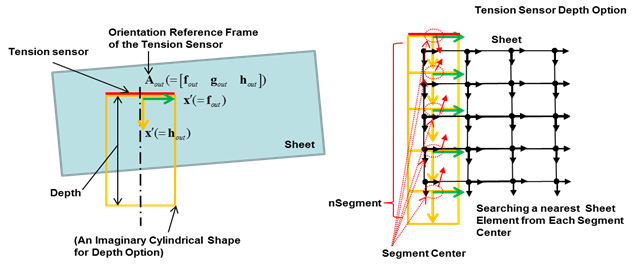
Figure 25.108 Tension Sensor Depth Option