6.4.4.8. Curve To Curve
A Curve To Curve Contact generates a force between one curve and the other curve.
The action curve and base curve must belong to two different bodies.
The contact force can be not only linear or exponential but also nonlinear spline characteristics to the contact penetration and its velocity.
The base or action curve can be approximated as multi lines with the Line option as shown in Figure 6.403.
The base or action curve can be approximated as a parameterized curve with the Curve option.
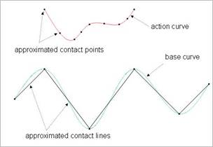
Figure 6.403 Approximated the base and action contact curves
6.4.4.8.1. Modeling Options
In the case of Curve To Curve contact, a curve geometry type is supported without base and action geometries when creating.
Curve, Curve
Curve: Selects a curve to define a base curve.
Curve: Selects a curve to define an action curve.
Curve, MultiCurve
Curve: Selects a curve to define a base curve.
MultiCurve: Selects some curves to define action curves.
Curve, Curve, Curve, Curve
Curve: Selects a curve to define a base curve.
Curve: Selects a curve to define an action curve.
Curve: Selects a curve to define another base curve.
Curve: Selects a curve to define another action curve.
MultiCurve, MultiCurve
MultiCurve: Selects some curves to define base curves.
MultiCurve: Selects some curves to define action curves.
6.4.4.8.2. Properties
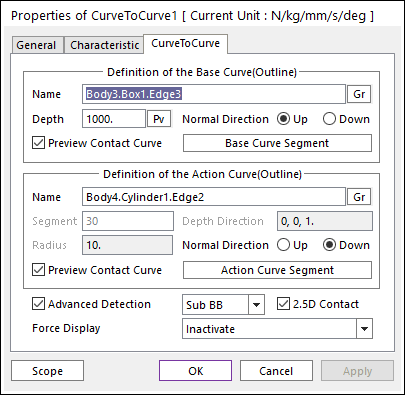
Figure 6.404 Properties of CurveToCurve dialog box
Definition of the Base Curve (Outline)
Entity Name: Defines the name of base curve or outline. The base curve or outline can be dispatched from the Working Window by clicking Gr.
Depth: Defines the depth of contact face of base curve. If the use inputs depth value as 1000, the range of depth is from -1000 to 1000. The user can change Depth as the parametric value by clicking PV.
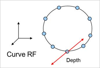
Figure 6.405 Definition of Depth
Normal Direction: Defines the normal direction of base curve or outline for a contact as shown in Figure 6.405.
The contact is available in the specified direction.
As selecting Up or Down, the user can change the contact direction of a base curve or outline.
If this page is activated, the normal direction is automatically shown on the Working Window.
Preview Contact Curve: If this option is checked, the points making the contact lines are shown on the Working Window as shown in Figure 6.405.
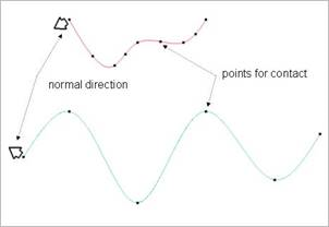
Figure 6.406 Preview of curve to curve contact
Base Curve Segment: Accesses Base Curve Segment dialog box.
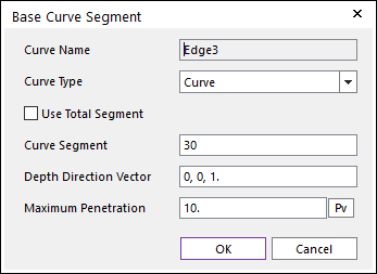
Figure 6.407 Base Curve Segment dialog box
Curve Name: This shows the name of the selected base contact geometry.
Curve Type: Select Line” or Curve” type for a contact curve. If the user selects the Line type, the contact curve can be approximated to multiple lines. If the user selects the Curve type, the contact curve is fitted to a parameterized curve. If the contact geometry has a curvature and the user wants to get a smooth contact force, the Curve type should be selected. Note that the advanced detection option should be activated before using this option.
Use Total Segment: If this option is selected, the user can make equally spaced contact points on the curve. For more information, click here.
Curve Segment: Defines the number of segments between a start node and an end node. For more information, click here.
Depth Direction Vector: Defines the direction vector of the contact surface extruded from the curve. The normal vector is determined by this direction.
Max Penetration: Defines the maximum penetration. If the penetration is greater than this value, the contact force is not generated. A good guideline is to set it at 3-10 times the expected penetration.
Definition of the Action Curve(Outline)
Entity Name: Defines the name of an action curve or outline. The base curve or outline can be dispatched from the Working Window by clicking Gr.
Segment: Shows the number of segments between nodes of the action curve defined in Curve Segment dialog box.
Radius: Shows the maximum penetration defined in Curve Segment dialog box.
Depth Direction: Shows the direction of depth defined in Curve Segment dialog box.
Advanced Detection: Select an advanced detection type as Full or Sub BB.
Full: All action contact lines are examined for a contact analysis.
Sub BB: The action curve is divided some sectors as shown in Figure 6.408 and the sub sectors are firstly examined whether the action curve interferes with the base curve. If the contact is expected, all lines that belong to the sub sector are examined.
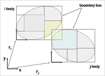
Figure 6.408 Advanced detection with the Sub BB type
2.5D Contact: The option decides the surface equation of 2.5D Contact.
If this option is not checked, the surface is using the polynomial equation.
If this option is checked, the surface is using the hermit polynomial. The default is checked.
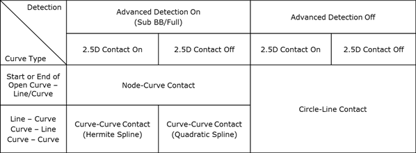
Figure 6.409 Curve Type as the option on/off Table
Force Display: Graphically displays the resultant force vector on the view window.