25.8.1. Sheet To Surface contact
A sheet is contacted with the 3D surface from CAD. The sheet is divided into several rectangular patches and the surface is divided into triangular patches. The edge or vertex of a rectangular patch of the sheet is contacted with the triangular patch. If the sheet is contacted with surface, the contact normal and friction forces are generated at the contact points as shown in Figure 25.67. The output force is the Base force which is acting on Base body Center Marker. The magnitude of contact force is equal with summation of forces of nodes on sheet.
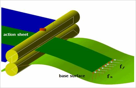
Figure 25.67 Example of a sheet to surface contact
A Sheet to Surface Contact generates a contact force between a sheet and a surface.
The sheet and surface must belong to two different bodies.
The contact force can be not only linear or exponential but also nonlinear spline characteristics to the contact penetration and its velocity.
The base surface and action sheet are approximated as triangular patches and rectangular patches as shown in Figure 25.68, respectively.
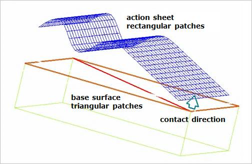
Figure 25.68 An example of a sheet to surface contact
25.8.1.1. Modeling Options
Surface, Sheet Group
Surface: Select a surface geometry to define a base entity.
Sheet= Group: Selects a sheet group to define an action entity.
Solid, Sheet Group
Solid: Select a solid geometry to define a base entity.
Sheet Group: Selects a sheet group to define an action entity.
25.8.1.2. Properties
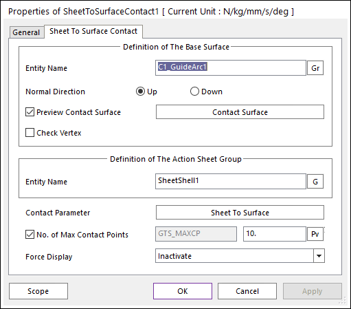
Figure 25.69 Sheet To Surface Contact property page
Entity Name of The Base Surface: Select the base surface by using Gr.
Normal Direction: Defines the normal direction of a base surface for a contact.
Preview Contact Surface: If this button is checked, the patches making the contact surface and its boundary box are displayed.
Contact Surface: Accesses Surface Patch dialog box as shown Figure 25.70.
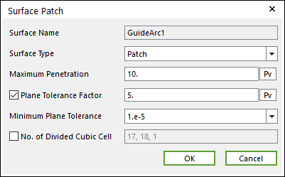
Figure 25.70 Surface Patch dialog box
Surface Type: Select the Patch or Surface type for a contact surface.
Patch: If the user selects the Patch type, the contact surface is approximated to multiple patches.
Surface: If the user selects the Surface type, the contact surface is fitted to a parameterized surface. If a contact geometry has a curvature and the user want to get a smooth contact force, the Surface type should be selected. Note that the Advanced Detection option should be activated before using the Surface type.
Max Penetration: Select the maximum penetration. If the penetration is greater than this value, the contact force is not generated. A good guideline is to set it at 3-10 times the expected penetration.
Plane Tolerance Factor: Specifies the surface tolerance factor as a value from 0 to 10. A smaller value produces a more refined patch. For more information, click here.
Minimum Plane Tolerance: If the decreasing plane tolerance factor has no effect on the patch refinement, the user should decrease the minimum plane tolerance. For very small surfaces (such as 1mm*1mm size), the user may need to decrease minimum plane tolerance to get an effective patch. Note that the default value of the minimum plane tolerance is 1.e-5.
No. of Divided Cubic Cell: Shows the number of cubic cells dividing a contact boundary box in each direction. This value is automatically calculated, but can be modified by the user.
Entity Name of The Action Sheet Group: Select the action sheet by using G.
Contact Parameter: Allows the user to modify contact parameters by clicking Sheet To Surface. In this dialog box, the user can modify the contact parameters of contact forces applied between the sheet and the surface. Refer to Contact Formulations for MTT3D.
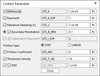
Figure 25.71 Contact Parameter dialog box
No. of Max Contact Points: Defines the number of max contact point for output. User can define this value from 1 to 5000. This value only affects Force Display and RPLT data about the contact points. The default value is 10.
Force Display: Graphically displays the all contact force vectors (the sum of the normal and tangential contact force) at each contact point up to the No. of Max Contact Point.
Check Vertex: When the size of a guide is smaller than that of a contacted shell element, the contact is not worked. In this case, if this option is on, the four vertexes of the guide are checked in the sheet-to-guide contact.