20.6.6.9. Rate Limiter
The Rate Limit block limits the rate of change of a signal. The rate of change is calculated by
\(rate=\frac{u_i-y_{i-1}}{t_i-t_{i-1}}\)
- where,
- \(u\) is the input signal\(y\) is the output signal\(t_i\) is the current simulation time step\(t_{i-1}\) is the previous simulation time step.
\(y_i=\Delta t \cdot R+y_{i-1}\)
- where,
\(R\) is the Rising rate parameter.
If rate is less than the Falling rate parameter, the output signal is calculated by
\(y_i=\Delta t \cdot F+y_{i-1}\)
- where,
\(F\) is the Falling rate parameter.
Dialog box
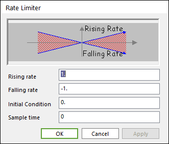
Figure 20.115 Rate Limiter dialog box
Parameter(s) |
Description |
Rising rate |
Enter the upper rate limit. |
Falling rate |
Enter the lower rate limit. |
Initial condition |
Enter the initial output signal |
Sample time |
Enter the time interval between samples. |
20.6.6.9.1. Example
We can test the Rate Limiter block with the CoLink model shown in the below figure The Sine block is configured to a frequency of 1rad/sec and an amplitude of 3. The Rate Limiter block Rising rate is set to 1 and Falling rate is set to -1. Initial Condition is set to 1. Set solver type to Fixed-Step, discrete (no continuous states), and let End time be 10.
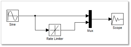
Figure 20.116 CoLink model
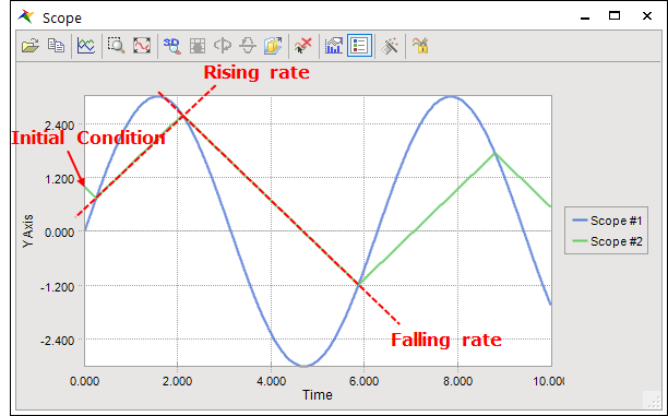
Figure 20.117 A result from scope