25.2.1. Contact Formulations for MTT3D
Contact Formulation
In a field of multi-body dynamics, one of the most known mathematical approximations of the dynamic behavior of a contact pair has been that one body penetrates into the other body with a velocity on a contact point. Here, a contact normal force can be defined as an equation of the penetration and its first differential of time as following equation.
\({{F}_{n}}=-k\delta -c\dot{\delta }\)
But, above equation has often been different from a physical phenomenon. Many people have studied to solve the contact problem, and some reasonable solutions have been proposed. For MTT3D, one of them is implemented for the contact normal force as following equation.
\({{F}_{n}}=-k{{\delta }^{m}}-c(\delta )\dot{\delta }\)
where, the order of m can compensate a spring force of restitution for nonlinearity. And the term of \(c(\delta )\) can prevent a damping force from being excessively generated when the penetration is very small. As shown in Figure 25.2, the user can understand the relation of a penetration and damping coefficient.
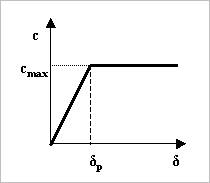
Figure 25.2 Boundary penetration and damping coefficient
Also, the damping force can be computed with the indentation exponent. In this case, the contact normal force can be obtained by
\({{f}_{n}}=k{{\delta }^{m1}}+c\dot{\delta }{{\delta }^{m3}}\)
where, \(k\) and \(c\) are the stiffness and damping coefficients which are determined by an experimental method, respectively. \(\delta\) and \(\dot{\delta }\) are a penetration and time differentiation of the penetration, respectively. The exponents \(m1\) generates a non-linear contact force and the exponent \(m3\) yields an indentation damping effect. When the penetration is very small, the contact force may be negative due to a negative damping force, which is not realistic. This situation can be overcome by using the indentation exponent greater than one.
Friction Formulation
A friction force can be determined as follows.
\({{f}_{f}}=\mu (\nu )\left| {{f}_{n}} \right|\)
where, \({{f}_{n}}\) and \(\mu\) are a contact normal force and a friction coefficient, respectively. By a tangential velocity of \(\nu\), the friction coefficient of \(\mu\) is determined as shown in Figure 25.3.
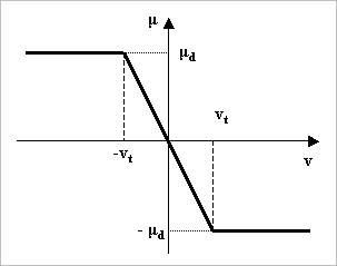
Figure 25.3 Friction force
where, \({{\nu }_{t}}\) and \({{\mu }_{d}}\) are a threshold velocity and a dynamic friction coefficient, respectively.
A friction coefficient is determined relatively to a tangential relative velocity at a contact point. In this time, two interpolation methods can be used. One is the STEP function and the other is the LINEAR function as shown in Figure 25.4.
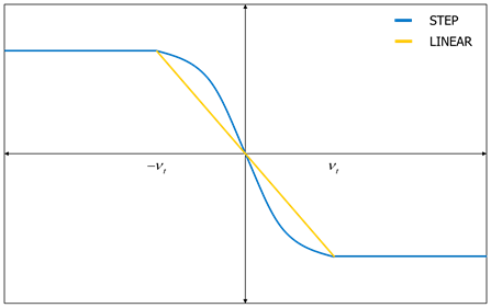
Figure 25.4 Friction forces generated by step and linear function.
The sheet is often transported by conveyer belt or other transmissions. To get these effects without a complex belt system, the Guide Velocity is introduced. The Guide Velocity is an imaginary velocity in order to generate a friction force of the tangential direction on the Guide entity. A friction force of the depth direction on the Guide entity is just generated by relative velocity between Sheet and Guide body. If the function is specified, the equation of friction force is changed as follows.
\({{f}_{f}}=-\mu (\nu -{{\nu }_{g}}){{f}_{n}}\)
If the Guide Velocity is applied, a plus rotational direction is the clockwise direction based on the z-direction of the highlighted reference frame of the selected guide.
The sheet is often over driven due to the elastic characteristics of a rubber roller and higher nip force. To get these effects without a complex rubber roller model, the Overdrive Factor of \(\alpha\) is introduced. If the function is specified in the roller to sheet contact parameter, the equation of friction force is changed as follows.
\({{f}_{f}}=-\mu (\nu -{{\nu }_{n}}\alpha \left| {{f}_{n}} \right|){{f}_{n}}\)
where, \({{\nu }_{n}}\) is the tangential velocity of a contacted roller.
The Overdrive Factor was developed for only “rolling direction”. So, it could not apply for depth direction.
RDF (Rebound Damping Factor) controls the rebound damping force when bodies are on restitution phase. Default is checked, and the value is 0.001. To see about the RDF, click here.
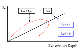
Figure 25.5 Effect of the RDF (Rebound Damping Factor)
Friction factor at Vertex of Sheet defines the factor to be multiplied contact friction coefficient only at the vertex of a sheet. The default value is 1.0. This option is included in the contact parameters dialog for the guide type entities.
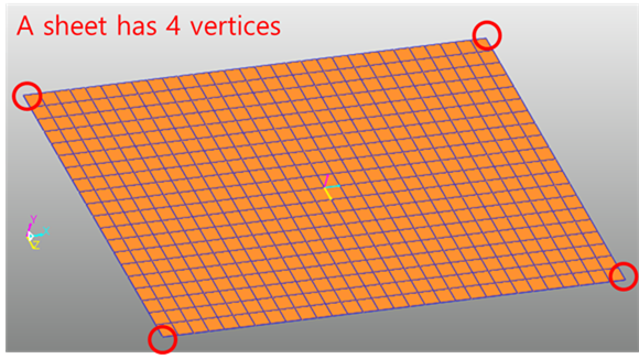
Figure 25.6 Vertex of a sheet