7.4.3. Joint
The lists of Joints include a result set about each joint. Especially, some joints report their relative coordinates, velocities and accelerations.
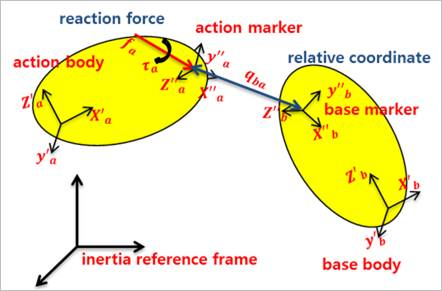
Figure 7.90 Definition of joint plot data
Pos_Relative: The relative coordinates as shown in Table 7.2.
Table 7.2 Definition of relative coordinates Joint
Index
Definition
Revolute
Pos1
The rotational angle of the z-axis of the action marker with respect to the z-axis of base marker.
Translational
Pos1
The translational displacement of the action marker relative to the base marker along the z-axis of base marker.
Spherical
Pos1
The Psi angle when the orientation of action marker with respect to the base marker is expressed in the Euler Psi - Theta -Phi angle.
Pos2
The Theta angle when the orientation of action marker with respect to the base marker is expressed in the Euler Psi - Theta-Phi angle.
Pos3
The Phi angle when the orientation of action marker with respect to the base marker is expressed in the Euler Psi - Theta -Phi angle.
Cylindrical
Pos1
The translational displacement of action marker relative to the base marker along the z-axis of base marker.
Pos2
The rotational angle of the z-axis of action marker with respect to the z-axis of base marker.
Universal
Pos1
The rotational angle of the x-axis of action marker with respect to the z-axis of base marker.
Pos2
The rotational angle of the x-axis of base marker with respect to the z-axis of action marker.
Planar
Pos1
The translational displacement of action marker relative to the base marker along the x-axis of base marker.
Pos2
The translational displacement of action marker relative to the base marker along the y-axis of base marker.
Pos3
The rotational angle of the z-axis of action marker with respect to the z-axis of base marker.
Screw
Pos1
The relative displacement from the base marker to the action marker in the z-axis of base marker.
Atpoint
Pos1
The Psi angle when the orientation of action marker with respect to the base marker is expressed in the Euler Psi - Theta -Phi angle.
Pos2
The Theta angle when the orientation of action marker with respect to the base marker is expressed in the Euler Psi - Theta -Phi angle.
Pos3
The Phi angle when the orientation of action marker with respect to the base marker is expressed in the Euler Psi - Theta -Phi angle.
Vel_Relative: The relative velocities as shown in Table 7.3.
Acc_Relative: The relative accelerations as shown in Table 7.3.
Table 7.3 Definition of relative velocities and accelerations Joint
Index
Definition
Revolute
Vel1 Acc1
The rotational velocity and acceleration of the z-axis of action marker with respect to the z-axis of base marker.
Translational
Vel1 Acc1
The translational velocity and the acceleration of action marker relative to the base marker along the z-axis of base marker.
Spherical
Vel1 Acc1
The x component of the rotational velocity and the acceleration of action marker relative to the base marker in the base marker reference frame.
Vel2 Acc2
The y component of rotational velocity and the acceleration of action marker relative to the base marker in the base marker reference frame.
Vel3 Acc3
The z component of the rotational velocity and the acceleration of action marker relative to the base marker in the base marker reference frame.
Cylindrical
Vel1 Acc1
The translational velocity and the acceleration of action marker relative to the base marker along the z-axis of base marker.
Vel2 Acc3
The rotational velocity and the acceleration to the z-axis of action marker with respect to the z-axis of base marker.
Universal
Vel1 Acc1
The z component of the rotational velocity and the acceleration of action marker relative to the base marker in the reference frame Vel2 of base marker.
Vel2 Acc2
The z component of the rotational velocity and the acceleration of base marker relative to the action marker in the reference frame of action marker.
Planar
Vel1 Acc1
The translational velocity and the acceleration of action marker relative to the base marker along the x-axis of base marker.
Vel2 Acc2
The translational velocity and the acceleration of action marker relative to the base marker along the y-axis of base marker.
Vel3 Acc3
The rotational velocity and acceleration of the z-axis of action marker with respect to the z-axis of base marker
Screw
Vel1 Acc1
The translational velocity and the acceleration of action marker relative to the base marker along the z-axis of base marker
Atpoint
Vel1 Acc1
The x component of the rotational velocity and the acceleration of action marker relative to base marker in the reference frame of base marker.
Vel2 Acc2
The y component of the rotational velocity and the acceleration of action marker relative to the base marker in the reference frame of base marker.
Vel3 Acc3
The z component of the rotational velocity and the acceleration of action marker relative to the base marker in the reference frame of base marker.
FM_Reaction_Force: The magnitude of the translational force acting at the action marker.
FX_Reaction_Force, FY_Reaction_Force, FZ_Reaction_Force:
PTSF, PTCV, CVCV: The x, y, and z components of the translational force applied at the action contact point in the inertia reference frame.
\(\mathbf{f}_a=\mathbf{f}_n+\mathbf{f}_f\)
The other joints: The x, y, and z components of the translational force acting at the action marker in the reference frame of base marker.
\(^b\mathbf{f}''=(\mathbf{A}_b\mathbf{C}_b)^T\mathbf{f}_a\)
TM_Reaction_Force: The magnitude of the torque acting at the action marker.
TX_Reaction_Force, TY_Reaction_Force, TZ_Reaction_Force:
PTSF, PTCV, CVCV: The x, y, and z components of the rotational torque applied at the action contact point in the inertia reference frame. The values are always zero.
\(\mathbf{\tau}_a = 0\)
The other joints: The x, y, and z components of the torque acting at the action marker in the reference frame of base marker.
\(^b\mathbf{\tau}_a''=(\mathbf{A}_b\mathbf{C}_b)^T\mathbf{\tau}\)
Driving_Force/Torque: The driving force or torque generated by the only specified Motion of Revolute, Translational, Cylindrical, Spherical, and Universal Joints.
Friction_Force/Torque: The friction force or torque generated by the specified Friction of Revolute, Translational, Cylindrical, and Screw Joints.
FX_Friction_Force, FY_Friction_Force, FZ_Friction_Force: The x, y, and z components of the friction force applied at the joint in the base reference frame. It applied Planar and Inplane Joints.
TX_Friction_Torque, TY_Friction_Torque, TZ_Friction_Torque: The x, y, and z components of the friction torque applied at the joint in the base reference frame. It applied Planar, Inplane, and Spherical Joints.
Joint1_Driving_Force/Torque: The driving force or torque of Revolute and Translational Joints on which generated by the specified Gear.
Joint2_Driving_Force/Torque: The driven force or torque of Revolute and Translational Joints on which generated by the specified Gear.
Driver_Driving_Force/Torque: The driving force or torque of Revolute, Translational and Cylindrical Joints on which generated by the specified Coupler.
Coupled_Driving_Force/Torque: The driven force or torque of Revolute, Translational and Cylindrical Joints on which generated by the specified Coupler.
Note
The driving force or torque applied on the joint should equal to the driving force and torque due to all couplers, gears and motions defined on the joint.
DM_FloatBase: For PTSF, PTCV, and CVCV, the magnitude of translational displacement of the base contact point with respect to the reference frame of base body.
DX_FloatBase, DY_FloatBase, DZ_FloatBase: For PTSF, PTCV, and CVCV, the x, y and z components of translational displacement of the base contact point with respect to the reference frame of base body.
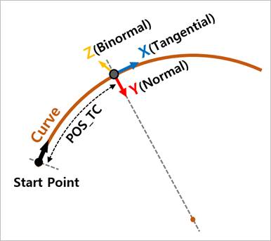
POS_TC: For PTCV, the curved distance between start point of curve and action marker.
Reaction_Force_Tangential: For PTCV, the translational force acting at the action marker in the tangent vector to a curve.
Reaction_Force_Normal: For PTCV, the translational force acting at the action in the vector perpendicular to the tangent vector to a curve.
Reaction_Force_Binormal: For PTCV the translational force acting at the action marker in the vector perpendicular to both the tangent and normal vectors to a curve.
DM_FloatAction: For CVCV, the magnitude of translational displacement of the action contact point with respect to the reference frame of the action body.
DX_FloatAction, DY_FloatAction, DZ_FloatAction: For CVCV, the x, y and z components of translational displacement of the action contact point with respect to the reference frame of action body.
NF_Contact: For CVCV, the translational force acting at the action contact point in the vector perpendicular to the tangent vector to action curve.
Base_Curve_Curvature: For CVCV, it becomes the curvature of base curve on the curve point.
For a space curve given parametrically in Cartesian coordinates by \(f(u)=(x(u),y(u),z(u))\), the curvature is
\[\begin{flalign} & \rho =\frac{\sqrt{{{\left( \ddot{z}\dot{y}-\dot{y}\ddot{z} \right)}^{2}}+{{\left( \ddot{x}\dot{z}-\ddot{z}\dot{x} \right)}^{2}}+{{\left( \ddot{y}\dot{x}-\ddot{x}\dot{y} \right)}^{2}}}}{{{\left( {{{\dot{x}}}^{2}}+{{{\dot{y}}}^{2}}+{{{\dot{z}}}^{2}} \right)}^{\frac{3}{2}}}} & \end{flalign}\]where the dot denotes differentiation with respect to the parameter \(u\).
Action_Curve_Curvature: For CVCV, it becomes the curvature of action curve on the curve point.