24.8. Guide Entities
Guides can be attached to the local mother body or a guide body, which is connected to a base body by a revolute joint and translational spring damper as shown in Figure 24.76. In general, arc guides, linear guides, and pguide edges are fixed on base body but as the user need an elastic effect of guides, guide body is useful.
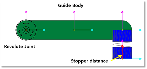
Figure 24.76 Guide body and Stopper distance
If the stopper distance is specified, the length of two points of the spring is not shorter than the defined value. Multiple linear guides, arc guides, and pguide edges can exist on a single guide part. If the guide part is deleted, all related guides are deleted.
Sheet and Guide Interactions
There are three types of guides.
One is an arc guide that is defined with a radius and an angle.
Another is a line guide that is defined with two points.
The third is a circle guide with contact properties that are similar to a roller.
Efficient contact formulation results from assuming that the arc and line guides only contacted the circular ends of a rigid segment. In contrast, the circle guide (PGuide) contacts all parts of each rigid segment.
Sheet and Arc Guide Interactions
The contact geometry of the arc guide is described as shown in Figure 24.77. The double primed coordinate system is the arc reference frame.
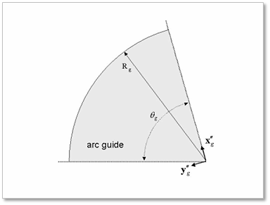
Figure 24.77 Contact geometry of arc guide
As shown in Figure 24.78, the relative displacement between a circular edge of rigid segment and arc guide can be computed as following equation.
where, \(\mathbf{r}_g\) and \(\mathbf{A}_g\) are the center position and orientation of the guide, respectively.
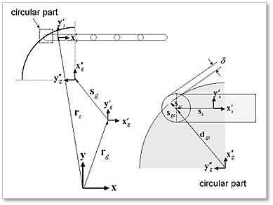
Figure 24.78 Sheet and arc guide interactions
The vectors of \(\mathbf{s}'_g\) and \(\mathbf{s}'_s\) are positions of the arc reference frame and the circular edge center position with respect to each body reference frame, respectively. If the vector of \(\mathbf{d}_{gs}\) is projected into the arc reference frame, the resultant vector can be represented as follows.
where, \(\mathbf{C}_g\) is the orientation matrix of the arc reference frame. The relative angle between x-axis of the arc reference frame and the resultant vector of (24.30) is within an arc angle.
where, \(\theta_g\) is the arc angle and \(\mathbf{f}''_g\) is a constant unit vector of \(\left\{\begin{matrix} 1 & 0 & 0 \end{matrix} \right\}^T\). If the condition of Eq. (3) is satisfied, the penetration is defined by the following equation.
where, \(R_g\) is a radius of the arc guide. The contact positions can be computed as follows.
where, \(\mathbf{u}''_n\) contains the normal direction vectors and is determined by the following equation.
The tangent direction vector is determined by the right hand rule. The relative velocity at the contact point can be determined as follows.
where, \(\mathbf{\omega}'_g\) contains the angular velocities of a roller and a segment with respect to each body reference frame, respectively. The contact forces at the contact point can be computed similarly as the sheet and roller interactions.
Sheet and Line Guide Interactions
The contact geometry of the line guide is described as shown in Figure 24.79. The double primed coordinate system is the line reference frame.
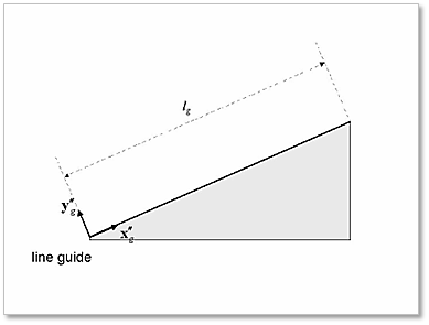
Figure 24.79 Contact geometry of line guide
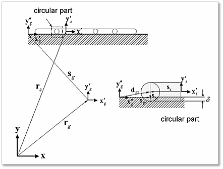
Figure 24.80 Sheet and line guide interactions
As shown in Figure 24.80, the relative displacement between a circular edge of a rigid segment and the line guide can be computed by the following equation.
where, \(\mathbf{r}_g\) and \(\mathbf{A}_g\) are the center position and orientation of the guide, respectively. If the vector of \(\mathbf{d}_{gs}\) is projected into the line reference frame, the resultant vector can be represented as follows.
where, \(\mathbf{C}_g\) is the orientation matrix of the line reference frame. The \(x\) component of (24.38) is less than a guide length.
where, \(l_g\) is the guide length and \(\mathbf{f}''_g\) is a constant unit vector of \(\left\{\begin{matrix} 1 & 0 & 0 \end{matrix} \right\}^T\). If the condition of Eq. (11) is satisfied, the penetration can be defined with the following equation.
The contact positions can be computed as follows.
The relative velocity at the contact point can be determined as follows.
where, \(\mathbf{\omega}'_g\) is angular velocities of a roller and a segment with respect to each body reference frame, respectively. The contact forces at the contact point can be computed similarly to the sheet and roller interactions.
Sheet and PGuide Edge Interactions
PGuide edge is dependent on a guide part. If PGuide edge is created, the circular guide to sheet contact is automatically created. Its contact type is a circle to line contact. As shown in Figure 24.81, when a sheet segment contacts PGuide edge, the normal positive direction is in the up or down direction of the y-axis of the segment body. The tangent direction is determined by the right-hand rule. The positive direction of Guide velocity is determined by the positive tangential direction.
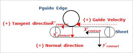
Figure 24.81 Pguide edge to Sheet contact
Guide Tolerance and Guide Velocity
To improve the numerical efficiency of a MTT2D model, Guide Tolerance is introduced as shown in Figure 24.82. The option is available with the Linear and Arc guide and it determines a stiffness coefficient k of the sheet to guide contact within a range. The stiffness coefficient can be determined as following equations.
\(k=step(x,-\epsilon_g,0,0,\epsilon_g,k_{max}) \quad -\epsilon_g \leq x \leq \epsilon_g\)
\(k=step(l,-x,-\epsilon_g,0,0,\epsilon_g,k_{max}) \quad l-\epsilon_g \leq x \leq 1+\epsilon_g\)
Where, \(x\) means a distance in Linear guide and a rotated angle in the arc guide, respectively. \(l\) is a length of the line and an angle of arc.
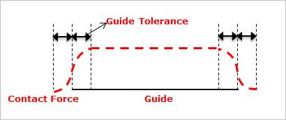
Figure 24.82 Guide tolerance
A sheet is often transported by a conveyer belt or other transfer devices. To get these effects without a complex belt system, Guide Velocity is introduced. If the function is specified, the equation of friction force is changed as follows.
\(F_f=\mu(\nu-\nu_g)\times F_n\)
If the Guide Velocity is applied, a plus rotational direction is the clockwise direction based on the z-direction of the highlighted reference frame of the selected guide.