6.1.4.3.1. Arc Revolution Surface
It allows the user to create an arc-revolution surface for defining Sphere To Arc Revolution Contact easily.
6.1.4.3.1.1. Modeling Options
The user can create a surface geometry by the following procedure.
Point, Direction, Point, Angle, Point, Direction, Angle
Point: Selects a point to define the arc center.
Direction: Defines an axis direction for generating the arc.
Point: Selects a point to define the start point of the arc.
Angle: Defines an angle of the arc.
Point: Selects a point to define the center point of the arc revolution.
Direction: Defines an axis direction of the arc revolution.
Angle: Defines a revolution angle.
Circle, Point, Direction, Angle
Circle: Selects a circular arc for the arc revolution.
Point: Selects a point to define the center point of the arc revolution.
Direction: Defines an axis direction of the arc revolution.
Angle: Defines a revolution angle.
Point: This option makes Arc Revolution directly. The user can modify its properties.
Point: Selects a point to define the center point of the arc revolution. And then an arc-revolution surface is created as the default value.
6.1.4.3.1.2. Properties
The user can modify the geometry information using the Arc Revolution Geometry property page.
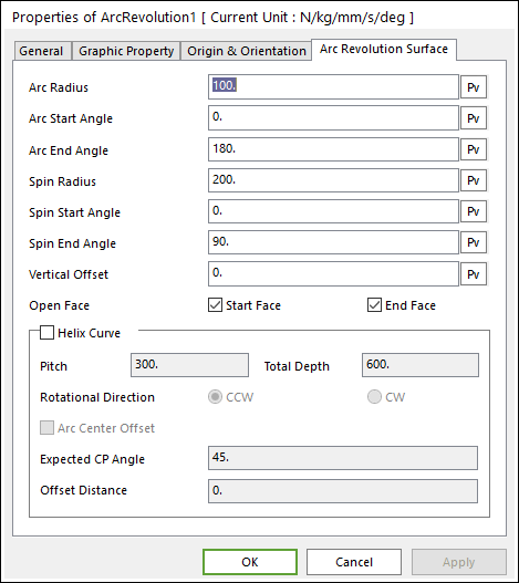
Figure 6.61 Arc Revolution Surface property page
Arc Radius: Defines the radius of the arc.
Arc Start Angle: Defines the start angle of the arc. The start angle of the arc is toward +Y axis.
Arc End Angle: Defines the end angle of the arc.
Spin Radius: Defines the radius of the arc revolution. It is toward +Z axis.
Spin Start Angle: Defines the start angle of the arc revolution. The start angle of the arc is toward +X axis.
Spin End Angle: Defines the end angle of the arc revolution.
Vertical Offset: Defines a offset distance to Z axis.
Open Face: Define a fan-shaped surface on Spin start angle and/or Spin end angle. The face surface is generated when the check box is unchecked.
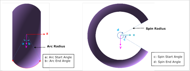
Figure 6.62 Dimensions
Helix Curve: If the user checks this option, then the arc center curve is defined on a helix curve.
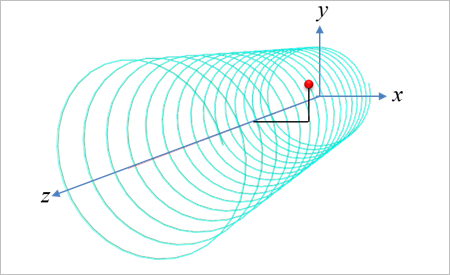
Figure 6.63 A center position on the generated helix curve
Pitch: Defines the pitch length of the helix center curve.
Total Depth: Defines the total depth of the helix center curve.
Rotational Direction: CCW(Counterclockwise), and CW(Clockwise) can be available.
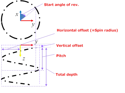
Figure 6.64 Definitions of Pitch, Total Depth, and Rotational Direction of the Helix Curve
Arc Center Offset: Defines additional options of the Helix Curve.
Expected CP Angle (Degree): Defines a negative direction of center offset. The angle means the definitions of the expected Contact Point.
Offset Distance: Defines an offset length in order to define a center point of a real arc-curve.
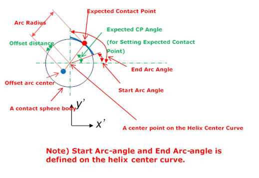
Figure 6.65 Definitions of Expected CP Angle and Offset Distance of the Arc Center Offset option of the Helix Curve
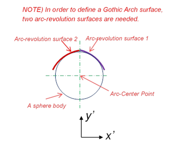
Note
The Gothic-Arch surface is not generated directly. It needs to assemble two Arc-Revolution Surfaces using Helix and Arc Center Offset options.