20.6.6.4. Limiter
The Limiter block imposes upper and lower limits. If the input signal is between the Upper and Lower limit values, the output signal is equal to the input signal. If the input signal is greater than the Upper value or less than the Lower value, the output signal is the Upper value or the Lower value, respectively.
Dialog box
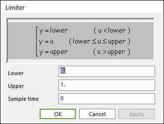
Figure 20.99 Limiter dialog box
Parameter(s) |
Description |
Upper |
Enter the upper limit. |
Lower |
Enter the lower limit. |
Sample time |
Enter the time interval between samples. |
20.6.6.4.1. Example
We can test the Limiter block with the CoLink model shown in the below figure The Sine block is configured to a frequency of 1rad/sec and an amplitude of 1. The Limiter block Lower is set to -0.5 and Upper is set to 0.5. Set solver type to Fixed-Step, discrete (no continuous states), and let End time be 1.
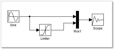
Figure 20.100 colink model
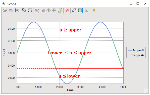
Figure 20.101 A result from scope