6.2.2.9. Constant Velocity
A constant velocity joint can model a constant velocity joint. This joint has two degrees of freedom. While remaining coincident and maintaining a constant velocity through the spin axis. This joint can be used to make a constant velocity situation in the base body and the action body about the z-axis of the joint
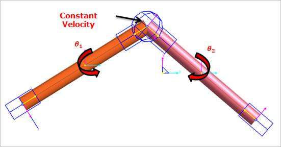
Figure 6.199 Constant Velocity Joint icon on Working Window
6.2.2.9.1. Modeling Options
The user can create a joint entity as follows.
Point, Direction, Direction, OrthoDirection
Point: Selects a point on two bodies to define the location of the constant velocity joint.
Direction: Defines the z-axis of the base marker as the axis of rotation.
Direction: Defines the z-axis of the action marker as the axis of rotation.
OrthoDirection: Defines the orthogonal direction.
Body, Body, Point, Direction, Direction, OrthoDirection
Body: Selects a base body of constant velocity joint.
Body: Selects an action body of constant velocity joint.
Point: Selects a point on two bodies to define the location of the constant velocity joint.
Direction: Defines the z-axis of the base marker as the axis of rotation.
Direction: Defines the z-axis of the action marker as the axis of rotation.
OrthoDirection: Defines the orthogonal direction.
6.2.2.9.2. Properties
The user can define motion, initial conditions, and friction force using the Joint page.
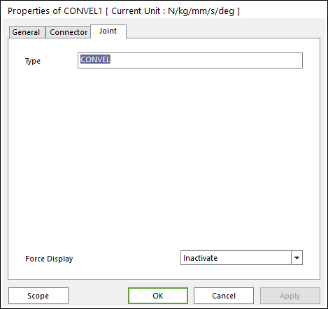
Figure 6.200 CONVEL property page [Joint page]
Type: Shows the type of joint.
Force Display: Displays the resultant force vector graphically on Working Window.