34.1.3.6. Push-rod & Center-pivoted Arm
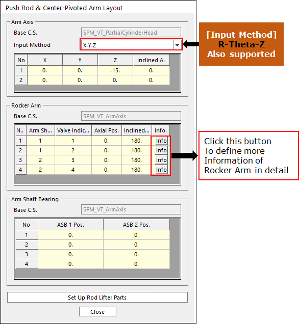
Click Rocker Arm & PushRod Layout in the Valve Global Data dialog box. And then the user can see the following dialog box.
Click Info in Rocker Arm layout dialog box. And then the user can see the following dialog box.
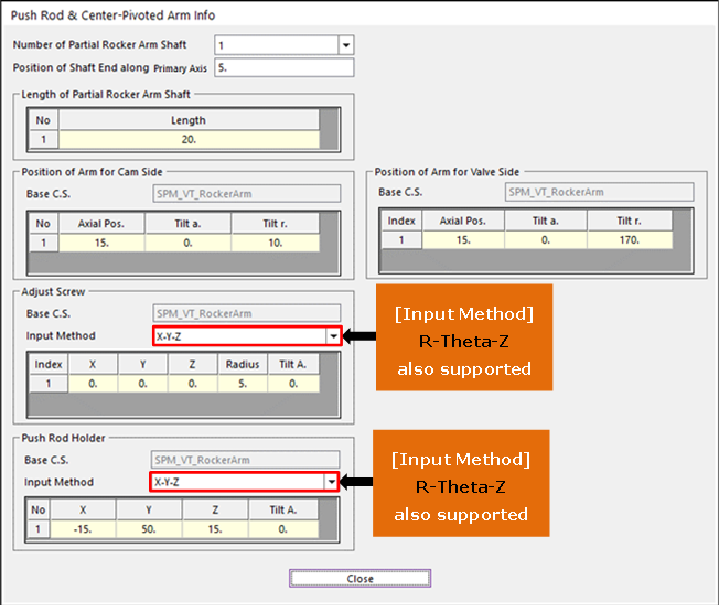
Figure 34.44 Push Rod & Center-Pivoted Arm Info dialog box
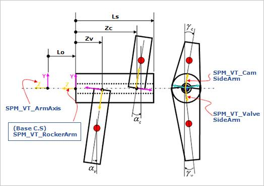
Figure 34.45 Rocker Arm Layout 1
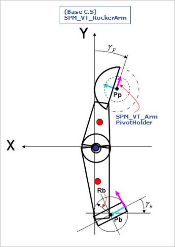
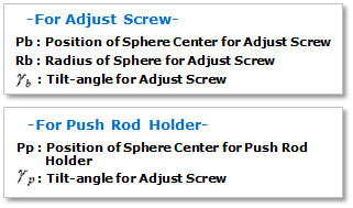
Figure 34.46 Rocker Arm Layout 2
Click Set Up Rod Lifter Parts in the Rocker Arm Layout dialog box. And then you can see the following dialog box.
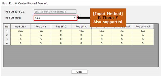
Figure 34.47 Set Up Rod Lifter Parts dialog box
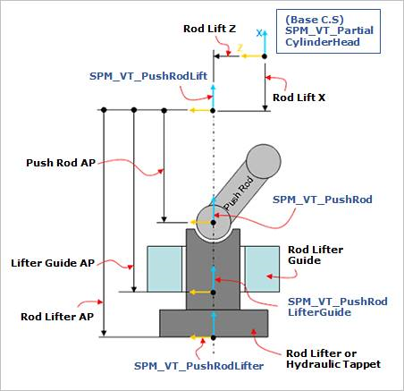
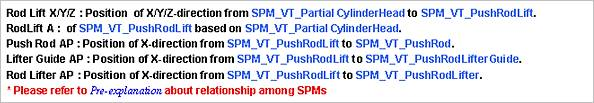
Figure 34.48 Rod Lifter Parts Layout
After setting up all parameters, click Close in the Push-rod & Center-pivoted Arm Layout dialog box.