26.8.4. Tension Sensor
This sensor allows the user to measure the tension of the segment. The segment passes the range of tension sensor and is the nearest to tension sensor.
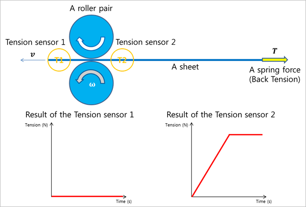
Figure 26.49 Tension Sensor
As shown in Figure 26.49, if a segment passes within the range of the sensor, the sensor output can be computed from the following equation.
\(\begin{aligned} & {{A}_{e}}\equiv \left[ \begin{matrix} f{}_{e} & {{g}_{e}} & {{h}_{e}} \\ \end{matrix} \right] \\ & {{A}_{t}}\equiv \left[ \begin{matrix} f{}_{t} & {{g}_{t}} & {{h}_{t}} \\ \end{matrix} \right] \\ & \left( \begin{aligned} & {{g}_{c}}={{g}_{e}} \\ & {{f}_{c}}={{g}_{c}}\times {{h}_{t}} \\ & {{h}_{c}}={{g}_{c}}\times {{f}_{c}} \\ \end{aligned} \right) \\ & {{A}_{c}}\equiv \left[ \begin{matrix} f{}_{c} & {{g}_{c}} & {{h}_{c}} \\ \end{matrix} \right] \\ & {{{{\sigma }'}}_{c}}={{A}_{c}}^{T}{{\sigma }_{c}}A{}_{c} \\ & {{{{\sigma }'}}_{c}}=\left[ \begin{matrix} {{{{\sigma }'}}_{xx}} & {{{{\sigma }'}}_{xy}} & {{{{\sigma }'}}_{xz}} \\ {{{{\sigma }'}}_{yx}} & {{{{\sigma }'}}_{yy}} & {{{{\sigma }'}}_{yz}} \\ {{{{\sigma }'}}_{zx}} & {{{{\sigma }'}}_{zy}} & {{{{\sigma }'}}_{zz}} \\ \end{matrix} \right] \\ & {{\sigma }_{o}}={{{{\sigma }'}}_{xx}} \\ \end{aligned}\)
- where,
- \({{\sigma }_{o}}\) is a stress value and the result of sensor.\({{{\sigma }'}_{c}}\) is the local stress tensor of the closest position of Element in the range of the sensor.\({{\sigma }_{c}}\) is the global stress tensor of the closet position of Element in the range of the sensor. In the case of shell element, \({{\sigma }_{c}}\) is a mid-stress acting on the neutral surface.\({{A}_{c}}\) is the reference frame of the output of the sensor. The x axis of \({{A}_{c}}\) is an expecting direction vector for acting a tension force.\({{A}_{t}}\) is the reference frame of the sensor. The z axis of \({{A}_{t}}\) is the normal direction vector of the tension sensor.\({{A}_{e}}\) is the reference frame of the closest position of Element in the range of the sensor. The y axis of the \({{A}_{e}}\)
26.8.4.1. Modeling Options
The user can create a tension sensor as follows.
Point, Distance
Point: Selects a point on a body to define the center of tension sensor.
Distance: Defines a range of region to measure output.
Note
The user should define the sensing target entity by using Tension Sensor property page.
Body, Point, Distance
Body: Selects a body to define the parent body of tension sensor.
Point: Selects a point on a body to define the center of tension sensor.
Distance: Defines a range of region to measure output.
Note
The user should define the sensing target entity by using Tension Sensor property page.
Assembled Body, Point, Distance
Assembled Body: Selects a beam assembly as a target entity.
Point: Selects a point on a body to define the center of tension sensor.
Distance: Defines a range of region to measure output.
Body, Assembled Body, Point, Distance
Body: Selects a body to define the parent body of tension sensor.
Assembled Body: Selects a beam assembly as a target entity.
Point: Selects a point on a body to define the center of tension sensor.
Distance: Defines a range of region to measure output.
26.8.4.2. Properties
The user can modify properties for the slip sensor such as a position, sensing target entity, and direction using Tension Sensor property page.
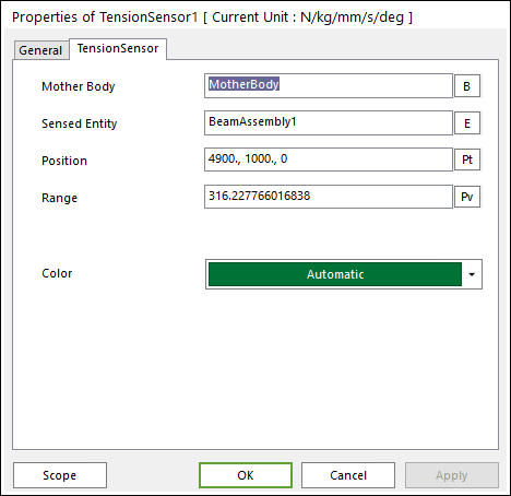
Figure 26.50 Tension Sensor property page
Mother Body: Selects the mother body of tension sensor.
Sensed Entity: Selects an assembled body as a sensing target entity.
Position: Defines the center of tension sensor.
Range: Defines the range of region to measure output.
Type: Selects the head(+x) or tail (-x) tension of assembly segment.
Color: Defines the color of tension sensor.