24.1. Overview
What are target applications for MTT2D?
The user can easily carry out a media path simulation for the two-dimensional movement of a sheet through a machine such as a printer, copier, fax, and other sheet-feeding machines
With MTT2D, the user can check for the potential jamming given:
Different sheet sizes, weights and stiffness
Different sheet properties due to temperature and humidity extremes
Different sheet velocities due to misalignment of drive-driven roller sets
Differences of roller velocities due to gap, wear or etc.
In the long term, MTT2D is the user essential partner for:
Modeling the flexible roller that contact the sheet through a patch whose size varies with the roller force
Modeling the attraction between the belt and the sheet due to vacuum forces, electrostatic attraction, etc.
Checking the steering of a belt due to pulley angle adjustments
Group for MTT2D
To make it possible to an easy and convenience GUI, a new concept of “group” is introduced. A group may include predefined sub-entities as bodies, joints, forces, and contacts.
For MTT2D, there are five group entities such as sheet, fixed roller, movable roller and guide body, and they make it possible to create and modify all sub-entities dependent on each group through a single operation. Each group is made of several sub-entities as summarized in the following table.
Group |
Entities |
Sheet |
Bodies, Joints, Forces, Contact geometry |
Guides |
Contact to Sheet, Contact geometry |
Fixed Roller |
Body, Joint, Contact to Sheet, Contact geometry |
MovableRoller |
Bodies, Joints, Contact to Roller and Sheet, Nip Force, Contact geometry |
Guide Body |
Body, Joint, Force |
Customized Contacts
There are two typical problems in simulating a media transport system.
The stepsize of the solver is small because the solver has to solve a numerically unstable system in which masses of sheet segment bodies are very small and they are in contact with guides or rollers.
The contact searching time is long for each time step because there are so many contact pair bodies.
Because of two problems, the simulation time is relatively long. To reduce the simulation time, RecurDyn includes new contact elements for MTT2D. They use a global detection method for checking a body pair in contact condition. The method has an advantage in that the amount of contact searching can be smaller than other methods for a system in which the position of most of rollers and guides are fixed on a point of a base body such as the ground or one carrier body. Most of sheet feeding machines such as a printer, copier or fax have this characteristic. All new contact elements are formulated in the 2D to reduce the number of Jacobian evaluations or computed equations compared to general contact elements. The following table summarizes the new contact elements that are developed for MTT2D. MTT2D does not support 3D contact.
Group |
Contacts |
Fixed Roller |
Roller to Sheet Contact |
MovableRoller |
Roller to Sheet Contact |
Roller to Roller Contact |
|
Roller to Dummy Contact for Soft Nip |
|
Roller to Base Body Contact for Maximum Gap |
|
Guide |
Sheet to Arc Guide Contact |
Sheet to Linear Guide Contact |
|
Guide Edge to Sheet Contact |
|
Sheet |
Sheet to sheet Contact |
About the coordinate systems
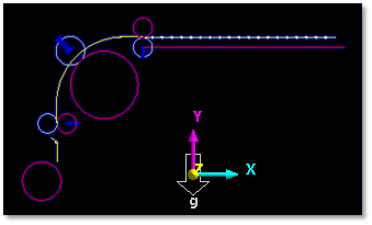
Figure 24.2 Coordinate system for the media transport toolkit
A media transport system must be modeled in the coordinate system defined in Figure 24.2. Therefore, all entities in MTT2D must be created in the X-Y plane.
Defining units
For MTT2D, it is very important to choose the user system of units property. In general, each sheet segment of the paper or film has a small mass. As the user divide the sheet into more segments, the mass of each segment body gets even smaller. The mass may become smaller than the numerical error in a unit system. The user must consider this when choosing a unit system. It is recommended that the user use the default unit system.
Step to create media transport system
Build the feeding system
Create a sheet
Modify the contact parameter
Check the assembly information
Run the simulation