29.4.1. Linear Guide
A 2D Linear Guide entity is supported in 2D Belt. The guide consists of several lines and the lines are contacted with segments automatically. This entity cannot be selected when assembling. So, it is recommended to add the linear guide as passing bodies in BeltAssembly2D property page.
29.4.1.1. Modeling Options
The user can create a linear guide as follows.
MultiPoint
MultiPoint: Selects some points to define the linear guide.
29.4.1.2. Properties
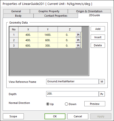
Figure 29.64 Linear Guide2D property page [2DGuide page]
The Linear Guide2D property page is shown in Figure 29.64. The parameters are explained below.
X,Y,Z: Defines points.
Add: Adds a row to the end of the table.
Insert: Inserts a row where the cursor is and move the current and later rows down.
Delete: Deletes the row where the cursor is and move the later rows up.
View Reference Frame: is the reference marker for geometry data of 2D guide. The contact force applied on the action body is reported as a force generalized on the defined marker. The default is Ground.Inertia Marker.
Depth: This is the graphic option to visualize the width of guide.
Normal Direction: Determines the contact direction.