6.2.2.6. Revolute
A revolute joint restricts the revolution only to the motion between two bodies. The joint has one rotational degree of freedom. The translation degree of freedom is 0. The origin of the revolute joint corresponds a marker. The rotational axis is the z-axis. The revolute joint can be located anywhere along the axis about which the joint’s parts can rotate in respect of each other. The orientation of the revolute joint defines the direction of the axis about which the joint’s parts can rotate in respect of each other. The rotational axis of the revolute joint is parallel to the orientation vector and passes through the location.
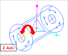
Figure 6.177 Revolute Joint icon on Working Window
6.2.2.6.1. Modeling Options
The user can create a joint entity as follows.
Point
Point: Selects a point on two bodies to define the location of the revolute joint. The normal axis of the working plane becomes the axis of rotation.
Point, Direction
Point: Selects a point on two bodies to define the location of the revolute joint.
Direction: Defines the direction of the z-axis of the revolute joint.
Body, Body, Point
Body: Selects a base body of the revolute joint.
Body: Selects an action body of the revolute joint.
Point: Selects a point to define the location of the revolute joint. The normal axis of the working plane becomes the axis of rotation.
Body, Body, Point, Direction
Body: Selects a base body of the revolute joint.
Body: Selects an action body of the revolute joint.
Point: Selects a point to define the location of the revolute joint.
Direction: Defines the direction of the z-axis of the revolute joint.
How to Define the Z-Axis (Direction)
By clicking the second point with respect to the first point.
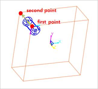
Figure 6.178 Clicking the second point
By clicking the straight line of the body.
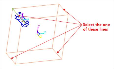
Figure 6.179 Navigation of the straight line
By clicking one of the axes of the marker.
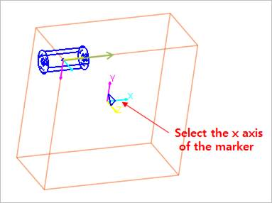
Figure 6.180 Navigation of the axis of the marker
By clicking the plane of the body. The z-axis of the revolute joint is defined as the plane’s normal direction of the body.
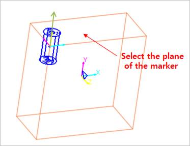
Figure 6.181 Navigation of the plane of the body
6.2.2.6.2. Properties
The user can define motion, initial conditions, and friction force using the Joint page.
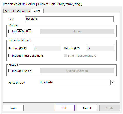
Figure 6.182 RevJoint property page [Joint page]
Motion: Defines the motion of the revolute joint. Refer to Motion.
Initial Conditions
Include Initial Conditions: If checked, enables the user-specified initial conditions (position and velocity).
Position (PV:R): The initial joint angle, specified in Degrees. If the user inputs the parametric value, the unit is Radian. This angle is the initial angular difference between the x-axis of the joint’s action marker and the x-axis of the joint’s base marker. The positive direction is defined by the right-hand rule.
Velocity (R/T): The initial velocity of revolute joint, specified in Radians/Time. The velocity is the angular velocity of the x-axis of the Action Marker relative to the x-axis of the Base Marker. The positive direction of the velocity follows the right-hand rule.
Strict Initial Conditions: Indicates that the initial condition settings should be strictly enforced. See Common UI Joint for more details.
If a revolute joint is connected to an FFlex body that is include in Position and Velocity Pre-Analysis and initial conditions are specified for the revolute joint, the initial rotation must be greater than -90 degrees and less than 90 degrees.
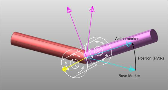
Figure 6.183 Position at Time 0 of simulation for a revolute joint with the initial position set to 30 degrees
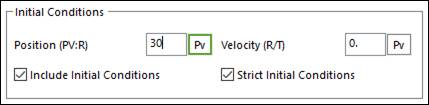
Figure 6.184 Initial condition settings for Figure 6.183
Include Friction: If this option is checked, the user can define the friction type of the revolute joint.
Force Display: Displays the resultant force vector graphically on Working Window.
6.2.2.6.2.1. Joint Friction
This defines the friction force which contains the stiction algorithm on a revolute joint. Include Friction option in Joint property page must be checked.
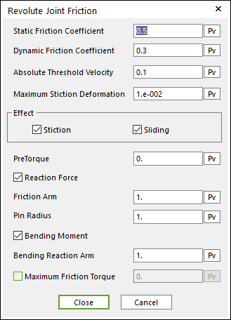
Figure 6.185 Revolute Joint Friction dialog box
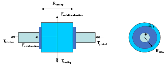
Figure 6.186 Configuration of Sliding and Stiction Friction Force on Revolute Joint
The frictional torque is calculated according to the following equation:
\({{T}_{friction}}=\mu ({{R}_{arm}}{{F}_{axialreaction}}+{{R}_{pin}}{{F}_{rotationalreaction}}+({{R}_{pin}}/{{R}_{bending}}){{T}_{bending}}+(1/{{\mu }_{s}}){{T}_{preload}})\)
Where, the inputs into the equation are defined in the following table:
Current Friction Coefficient |
\(\mu\) |
The coefficient of friction calculated during the simulation is a function of the relative velocity between the body surfaces. |
Static Friction Coefficient |
\({{\mu }_{s}}\) |
The coefficient of friction is zero at a zero velocity, but it smoothly transitions to the static coefficient of friction at Absolute Threshold Velocity (\(\Delta v\)). |
Effect |
Checks Stiction or Sliding
\({{\mu }^{sliding\text{ }only}}=-{{\mu }_{v}},\text{ }{{\mu }_{v}}^{\max }={{\mu }_{d}}\)
\({{\mu }^{stiction\text{ }only}}=-\left( 1-\beta \right){{\mu }_{\delta }}-{{\mu }_{v}},\text{ }{{\mu }_{v}}^{\max }={{\mu }_{s}}\)
|
|
Pre Torque |
\({{T}_{preload}}\) |
A constant frictional torque that acts during the entire simulation. |
Reaction Force |
\({{F}_{axialreaction}}\) |
The force in the joint calculated during the simulation in the direction normal to the rotational axis. |
\({{F}_{rotationalreaction}}\) |
The force in the joint calculated during the simulation in the direction along the rotational axis. |
|
Friction Arm |
\({{R}_{arm}}\) |
The radius of the larger surface geometry in the revolute joint. |
Pin Radius |
\({{R}_{pin}}\) |
The radius of the smaller surface geometry in the revolute joint. |
Bending Moment |
\({{T}_{bending}}\) |
The calculated torque that acts at right angles to the rotational axis. |
Bending Reaction Arm |
\({{R}_{bending}}\) |
The length of the middle contact surface along the rotational axis. |
Maximum Friction Torque |
\({{T}_{\max }}\) |
Collisions during contact as well as transitions during sliding forces can result in force spikes. High frictional torques can result from these spikes. This option allows a maximum friction torque to be defined that should correspond to the maximum expected steady-state force. |
Stiction causes the coefficient of friction to be ramped up to the static coefficient of friction once the movement of the surfaces has reached the maximum stiction deformation.
If the joint velocity is greater than Absolute Threshold Velocity,
\(\mu ={{\mu }_{v}}\)
Where, \({{\mu }_{v}}\) is determined by Figure 6.190.
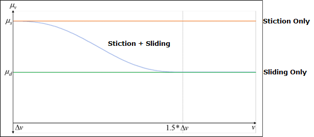
Figure 6.187 \({{\mu }_{v}}\) Graph
If the joint velocity is less than Absolute Threshold Velocity, \(\mu =-(1-\beta ){{\mu }_{\delta }}-{{\mu }_{v}}\)
Stiction: \(\beta\), \({{\mu }_{\delta }}\), \({{\mu }_{v}}\) is determined by Figure 6.191.
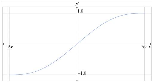
Figure 6.188 \(\beta\) Graph, when \(v<\Delta v\)
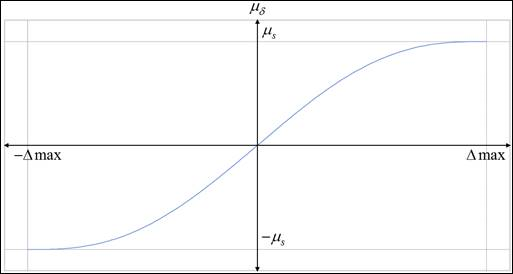
Figure 6.189 \({{\mu }_{\delta }}\) Graph, when \(v<\Delta v\)
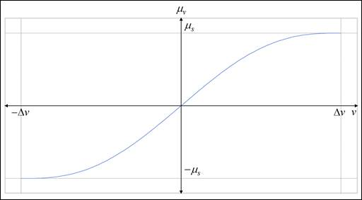
Figure 6.190 \(\beta\), \({{\mu }_{\delta }}\), \({{\mu }_{v}}\) Graph
Sliding: \(\beta =1\), \({{\mu }_{\delta }}=0\), \(\text{ }{{\mu }_{v}}^{\max }={{\mu }_{d}}\)
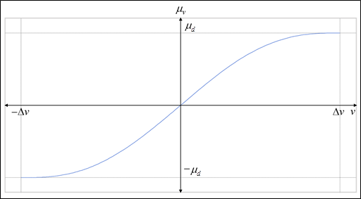
Figure 6.191 \({{\mu }_{v}}\) Graph, when \(v<\Delta v\)
Static Friction Coefficient |
\({{\mu }_{s}}\) |
The coefficient of friction is zero at a zero velocity, but it smoothly transitions to the static coefficient of friction at Absolute Threshold Velocity (\(\Delta v\)). |
Dynamic Friction Coefficient |
\({{\mu }_{d}}\) |
The coefficient of friction smoothly transitions to Dynamic Friction Coefficient as the sliding velocity exceeds the Absolute Threshold Velocity (\(\Delta v\)). |
Absolute Threshold Velocity |
\(\Delta v\) |
Defines the sliding velocity at which the coefficient of friction is set to the Static Friction Coefficient. Note that the transition to Dynamic Friction Coefficient is complete when the sliding velocity reaches 150% of Absolute Threshold Velocity. |
Maximum Stiction Deformation |
\(\Delta max\) |
The distance (offset) that the contact surfaces move from each other when the coefficient of friction transitions from a value of zero to the static coefficient of friction. |