32.2.1. Engine Block
An engine block is composed of a single body. The shape of engine block is automatically determined by other parameters.
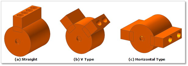
Figure 32.34 Engine Block
Terminology
Reference Parametric Marker
Distance between Crank Center and Cylinder Top/Bottom
Cylinder Diameter
32.2.1.1. Modeling Options
Click the E.Block icon of the Crank group in the Crank tab. The user can see the Crank Component - EBlock dialog box.
The position of an engine block is automatically defined
Only one engine block should exist at the current system.
If the engine block already exists, the user cannot create engine block anymore.
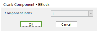
Figure 32.35 Crank Component-EBlock dialog box
Click OK.
32.2.1.2. Properties
Click the right mouse button of engine block body to choose Properties on right-click menu. The user can modify the property of engine block in following dialog.
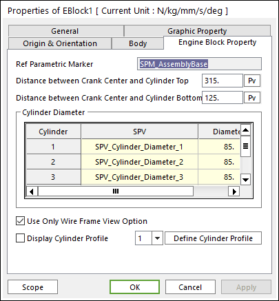
Figure 32.36 Engine Block property page
Reference Parametric Marker controls the position of engine block. It is also special parametric marker (SPM).
Distance between Crank Center and Cylinder Top/ Bottom: Refer to Figure 32.37.
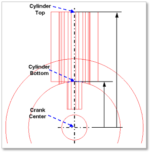
Figure 32.37 Distance between Crank Center and Cylinder Top/Bottom
Cylinder Diameter: Is also special parametric value. The user can modify the parametric value in this section.
These values are enlisted in special parametric value list.
The name and value of each parameter are shown.
Use Only Wire Frame View Option: if it is checked, it is useful to see internal bodies.
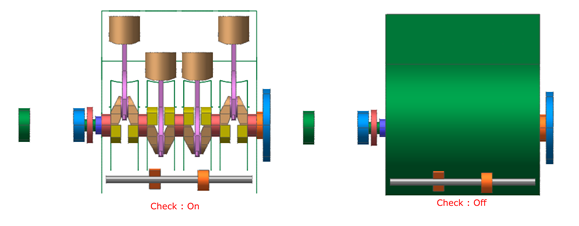
Display Cylinder Profile: If it is checked, it is possible to confirm cylinder profile associated with contact between a cylinder and a piston.
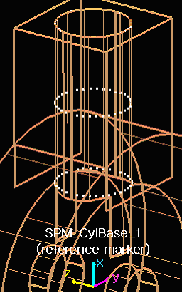
Figure 32.38 Display Cylinder Profile
Define Cylinder Profile: Changes the values to define cylinder profile which is based on SPM_CylBase_i (reference marker). Refer to following example.
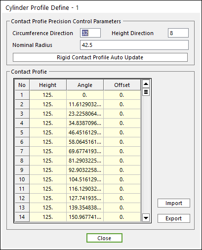
Figure 32.39 Cylinder Profile Definition dialog box
To modify the values such as Nominal Radius, Angle and Height, the user should change the value (radius, angle) related with circumference direction, and then change the value (height) related with the height direction.
Enter the values of Circumference Direction / Height Direction (ex, 3, 2) and then click Rigid Contact Profile Auto Update. And the user can confirm Cylinder Profile which is based on SPM_CylBase_i (reference marker).
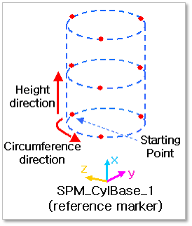
Figure 32.40 An example of Display Cylinder Profile