30.2.3. Multiplex Sprocket
The chain converts rotational power to pulling power, or pulling power to rotational power, by engaging with the sprocket. In general, a chain system employs single sprocket consisted of teeth and the main body named sprocket hub. Exact sprocket tooth geometry must be defined. The sprocket tooth geometry data can be created, edited, exported or imported from a predefined data file.
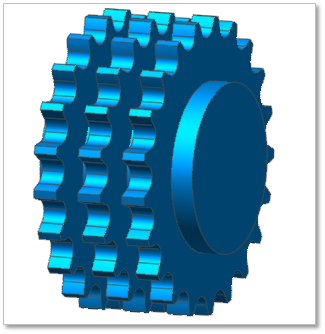
Figure 30.25 Multiplex Sprocket geometry
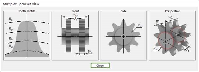
Figure 30.26 Multiplex Sprocket dimension information
Wt |
Width of Teeth |
Rw |
Sprocket Wheel Radius |
Ww |
Width between Wheels |
Pt |
Transverse Pitch |
Rd |
Dedendum Circle Radius |
Rb |
Base Circle Radius |
Rp |
Pitch Circle Radius |
Ra |
Addendum Circle Radius |
30.2.3.1. Modeling Options
The user can create a sprocket as follows.
Point, WithDialog
Point: Selects a point to define the center of the sprocket.
WithDialog: Modifies the property for the sprocket. The sprocket is created with clicking OK.
30.2.3.2. Properties
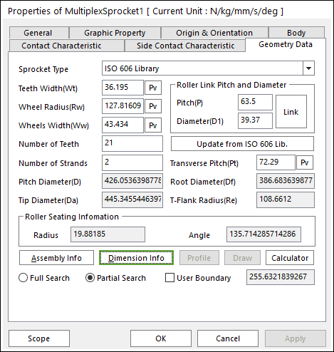
Figure 30.27 Multiplex Sprocket property page [Geometry Data page]
The Multiplex Sprocket property page is shown in Figure 30.27. The parameters are explained below. In order to understand the geometry, refer to Dimension Information.
Number of Stands: Defines the number of sprockets.
Transverse Pitch (Pt): Defines the distance between Sprockets.
All data is same to Roller Sprocket. For more information, click here.
Contact between a Multiplex Sprocket and a Multiplex Link
The sprocket is in contacts with the chain link in the two parts.
The sprocket teeth surface – the roller of chain link
The sprocket teeth surface - the inner plate surface of chain link
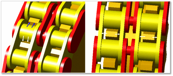
Figure 30.28 Contact between a multiplex sprocket and multiplex chain links