24.3. Sheet Group
Definition of Sheet and Contact Geometry
An accepted two-dimensional approximation of the proper behavior of a sheet has been a series of rigid segments connected by revolute joints and rotational spring-dampers as shown in Figure 24.12. Note that the depth of each segment is assumed to be 1mm. Mass properties of the sheet, rollers, any moving guides, etc. should corresponding to a slice of the physical device that is 1mm in depth direction.
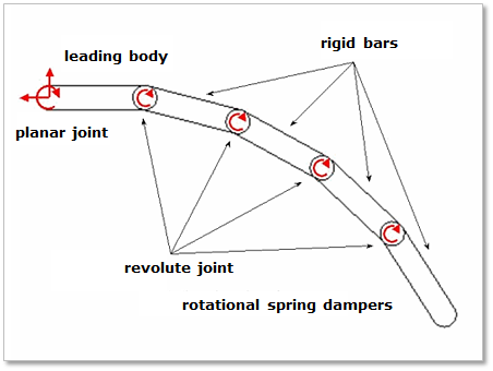
Figure 24.12 Definition of Sheet
The sheet is divided into several rigid segments with mass properties. The mass and inertia moment of each rigid segment are defined as follows.
- where,
- \(\rho\) is the sheet density\({{t}_{s}}\) and \({{L}_{s}}\) are the thickness and the length of each rigid segment\({{d}_{s}}\) is 1mm
The leading body is connected to a ground by a planar joint to guarantee an in-plane motion. The planar joint has one rotational and two translational degrees of freedom. i body is connected to the (i + 1) body by a revolute joint and rotational spring damper. The revolute joint has one rotational degree of freedom between two rigid segments. The relative angle of \({{\theta }_{i(i+1)}}\) is directly integrated. The torque of the rotational spring-damper is computed as following.
- where,
- \({{\theta }_{i(i+1)}}\) and \({{\dot{\theta }}_{i(i+1)}}\) are relative angles and angular velocities of the revolute joints.The stiffness and damping coefficients of \(k\) and \(c\) can be computed by (24.11) and (24.12), respectively.\(E\) and \({{C}_{s}}\) are the young’s modulus and the structural damping factor of the sheet.
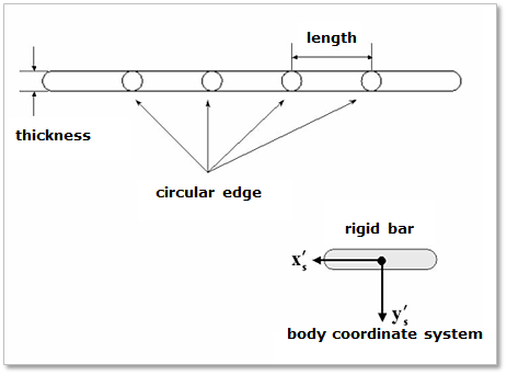
Figure 24.13 Contact geometry of a two dimensional sheet
The contact geometry of a sheet is described as a box and two circles as shown Figure 24.13. The x-axis of the body reference frame of each rigid segment is defined along the longitudinal direction and the y-axis is defined by right hand rule. The mass center of each rigid segment is located at the center point of the box. To generate a continuous contact force, two circles are located on both sides of the box.
The advantage of this approach is a good visual appearance of the sheet under severe bending conditions. The disadvantages of this approach are the lack of continuity between rigid segments that may cause problems with the contact modeling, since the leading and trailing edges of each segment are rigid. These disadvantages are overcome by introducing a circular edge at the leading and trailing points of each rigid segment.
Coordinate System of Sheet
To compute the mass of the sheet segment body, the sheet is described as box with a depth of one length unit. The center marker is located at the central point of the box and its orientation is dependent on the direction used when the Sheet is created as shown in Figure 24.14.
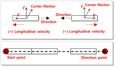
Figure 24.14 Coordinate system of Sheet
The x-axis of the center marker is in the opposite direction of the defining Direction. The z-axis of the center marker is always in the same direction as the z-axis of Inertia reference frame and the y-axis is determined by the right-hand rule as shown in Figure 24.14. If the user applies a positive initial velocity of sheet on user’s model, the sheet moves into plus direction of the x-axis of the center marker of a segment body. The joint and force markers of each segment body are located at both ends and their orientations are same as the orientation of the center marker.
Sheet Curl Radius
A curl radius can be applied to a sheet as shown in Figure 24.15. In its relaxed state the sheet bends with a curvature that matches the radius when a non-zero radius is defined. A positive radius value rotates successive sheet bodies in a counter-clockwise direction as the user proceeds from the starting point to the end of the sheet. The sheet in the figure has a negative curl radius. With a positive curl radius applied to a horizontal sheet with the Starting Point to the left, the ends point up. With a positive curl applied to a horizontal sheet with the Starting Point to the right, the ends point down.
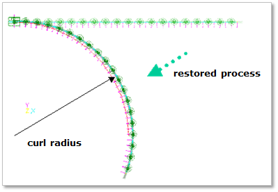
Figure 24.15 Restoration force for a curl radius