6.2.4.3. PTSF
A PTSF joint can do modeling a continuous contact model between a specific point and a specific UV surface. The PTSF joint icon is located joint group in the Professional tab.
6.2.4.3.1. Modeling Options
The user can create a joint entity as follows.
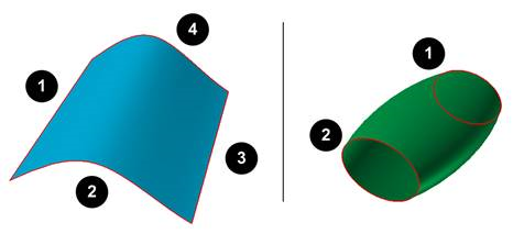
Surface(4-sided Surface, UV Surface), Point
Surface(4-sided Surface, UV Surface): Selects a 4-sided surface or UV surface.
Point: Selects a point on the body to define the location of the PTSF joint. The.
Surface(4-sided Surface, UV Surface), Body, Point
Surface(4-sided Surface, UV Surface): Selects a 4-sided surface of UV surface.
Body: Selects an action body of the PTSF joint.
Point: Selects a point on the body to define the location of the PTSF joint.
Note
The user must use the surface which has 2 or 4 edges when creating the PTSF joint.
6.2.4.3.2. Properties
The user can define initial conditions using the Joint tab on the properties page.
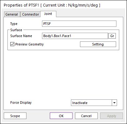
Figure 6.234 PTSF property page [Joint tab]
Type: Shows the type of joint.
Surface
Surface Name: Changes the selected surface by using Gr.
Preview: Shows patches of the surface and the U, V direction.
Setting: Accesses the Surface Patch dialog box as shown in the below figure.
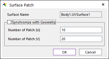
Figure 6.235 Surface Patch dialog box
Surface Name: This shows the name of the surface geometry.
Synchronize with Geometry: If the surface is a UV surface, this option is enabled. If the option is checked, the U and V value of the UV surface geometry are used for the PTSF surface patch option. If it is not checked, the numbers of UV patches in this dialog box are used for the PTSF surface patch option.
Number of Patch (U): This value defines the number of quad patches in U direction on the UV surface.
Number of Patch (V): This value defines the number of quad patches in V direction on the UV surface.
Force Display: Displays the resultant force vector graphically on Working Window.