21.2.3.1. Design Parameters
Design Parameters are used as the candidate set of design variables. The follows are the steps and options for definition
21.2.3.1.1. Step for definition
Select the Parameter icon of the Parameter group in the AutoDesign tab.
Figure 21.11 Parameter icon of the Parameter group in the AutoDesign tab
Select create option (shown in Figure 21.12)
Design parameter must be defined as one of five types. The types are Direct Relation’ and FEShapes1~4. The detail explains is in Option of the definition design parameter.
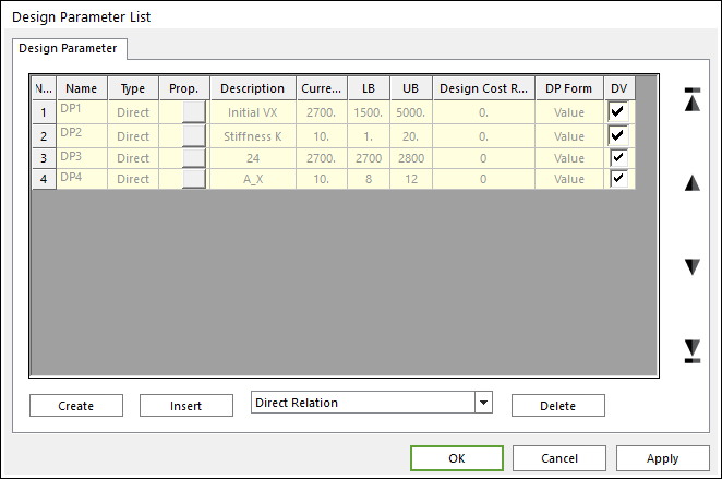
Figure 21.12 Design Parameter List dialog box
Click the Create or Insert button (in Figure 21.12)
Define conditions of a design parameter
In design parameter dialogue, one can define Lower Bound and Upper Bound of design variable. The detail conditions for each type of design parameter is explained with create options in the next section.
21.2.3.1.2. Option of the definition design parameter
Direct Relation
One can define the relationship between the design variable and the parametric value. AutoDesign change the value of design variables in its processes. Then, the parametric values linked by this option are internally changed. Finally, analysis parameters modeled by these parametric values are sequentially changed. Figure 21.13 shows the sequence of these relations.
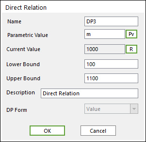
Figure 21.13 Direct Relation dialog box
Parametric Value: ‘Pv’ button change the dialogue as ‘Parametric Value List’. Then one can select the parametric value related design variable.
Current Value: R button can refresh the parametric value.
‘Lower Bound’, ‘Upper Bound’: The boundary of the defined design parameter.
Description: One can describe the design variable in the ‘Description’ blank.
FEShape1: Translation Relation
As shown in Figure 21.14, one wants to change the initial position of node set. Then, he uses this design variable type.
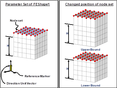
Figure 21.14 FEShape1: Translation Relation
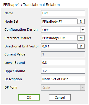
Figure 21.15 FEShape1: Translation Relation dialog box
Node Set: One can define the node set in the blank or navigate from window using ‘N’ button.
Configuration Design: you can select ‘on’ or ‘off’. For example, if you select ‘on’, node set-A is moved as Figure 21.16 It is note that the relative positions are maintained among nodes in the node set but their global position is moved. If you select ‘off’, node set-A is moved as Figure 21.16. Their relative positions and global positions are changed simultaneously. The default option is ‘off’.
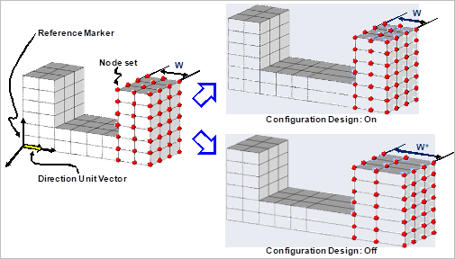
Figure 21.16 The role of configuration design switch
Reference Marker: Allows you to write the name of the reference marker in the blank or navigate from window using the M button. This is the reference mark to measure the distance of node set.
Directional Unit Vector: One can define unit vector in the blank or navigate from window using ‘D’ button. This is the direction of changing the shape of node set.
Current Value: ‘1’ is the scale factor represented the original position. All positions of the node set are measured from the reference coordinate. Then, these values are saved the current positions of node set. As all nodes have different positions, the scale factor is employed for design variable.
Lower Bound, Upper Bound: The lower and upper bound of the scale factor of node positions. Suppose that Lower and upper bounds are defined as 0.7 and 1.3 respectively. Then, during the optimization process, the positions of the selected node set can be changed during \(\pm 30\%\) of the current position along the directional unit vector at the reference marker.
Description: One can describe the design variable in the ‘Description’ blank.
FEShape2: Cylindrical Distance
As shown in Figure 21.17, this design variable type can change the position of node set along the radial direction. To do this, one selects the node set and define the reference mark and the center axis. Then, he defined the lower and upper bounds of the position scale factor.
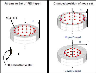
Figure 21.17 FEShape2: Cylindrical Distance
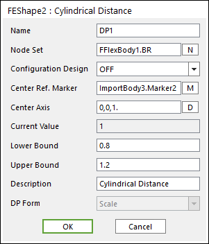
Figure 21.18 FEShape2: Cylindrical Distance dialog box
Node Set: One can define the name of the node set in the blank or navigate from window using ‘N’ button.
Configuration Design: This switch should be ‘off’. The relative positions are not maintained along the radius direction. If one wants to move the node set radial direction, he can use the translation relation.
Center Ref. Marker: One can define the name of the reference marker in the blank or navigate from window using ‘M’ button.
Center Axis: One can input unit vector in the blank or navigate from window using ‘D’ button. The radial distance of node set is measured from this axis at the center reference marker.
Current Value: ‘1’ is the scale factor represented the original position. All positions of the node set are measured from the reference axis. Then, these values are saved the current positions of node set. As all nodes have different positions, the scale factor is employed for design variable.
Lower Bound, Upper Bound: The lower and upper bound of the scale factor of node positions. Suppose that Lower and upper bounds are defined as 0.7 and 1.3 respectively. Then, during the optimization process, the positions of the selected node set can be changed during ± 30 % of the current position along the radial directions from the center axis.
Description: One can describe the design variable in the ‘Description’ blank.
FEShape3: Spherical Distance
As shown in Figure 21.19, the positions of nodes can be changed along the radial directions from the center point of the reference marker. Suppose that one wants to change the ball bearing shape. Then, he can use this design variable type. First, he defines the node set for shape optimization. Next, he defines the center reference marker and the lower and upper bound of position scale factor.
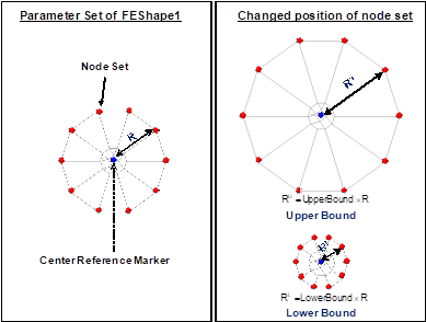
Figure 21.19 FEShape3: Spherical Distance
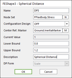
Figure 21.20 FEShape3: Spherical Distance dialog box
Node Set: One can define the name of the node set in the blank or navigate from window using ‘N’ button.
Configuration Design: This switch should be ‘off’. The relative positions are not maintained along the radius direction. If one wants to move the node set radial direction, he can use the translation relation.
Center Ref. Marker: One can write the name of the reference marker in the blank or navigate from window using ‘M’ button.
Current Value: ‘1’ is the scale factor represented the original position. All positions of the node set are measured from the reference point. Then, these values are saved the current positions of node set. As all nodes have different positions, the scale factor is employed for design variable.
Lower Bound, Upper Bound: The lower and upper bound of the scale factor of node positions. Suppose that Lower and upper bounds are defined as 0.7 and 1.3 respectively. Then, during the optimization process, the positions of the selected node set can be changed during ± 30 % of the current position along the radial directions from the center point.
Description: One can describe the design variable in the ‘Description’ blank.
FEShape4: Angular Relation
As shown in Figure 21.21, the position of node set can be rotated. The positions of node set are rotated from the reference plane at the reference marker.
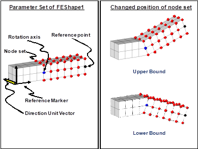
Figure 21.21 FEShape4: Angular Relation
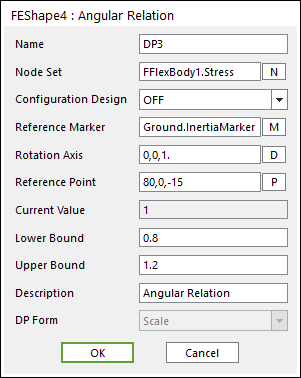
Figure 21.22 FEShape4: Angular Relation dialog box
Node Set: One should define the name of the node set in the blank or navigate from window using ‘N’ button.
Configuration Design: When you select ‘on’, the selected node set are rotated and maintained the relative distance which is shown in Figure 21.22. Otherwise, their relative positions are changed from the reference plane. The default option is ‘off’.
Reference Marker: One should write the name of the reference marker in the blank or navigate from window using ‘M’ button.
Rotation Axis: One can input unit vector in the blank or navigate from window using ‘D’ button.
Reference Point: One should define the position of the point in the blank or navigate from window using ‘P’ button. The reference plane is determined by using the rotation axis and this reference point.
Current Value: ‘1’ is the scale factor represented the original position. All angles of the node set are measured from the reference plane. Then, these values are saved the current positions of node set. As all nodes have different angles, the scale factor is employed for design variable.
Lower Bound, Upper Bound: The lower and upper bound of the scale factor of node positions. Suppose that Lower and upper bounds are defined as 0.7 and 1.3 respectively. Then, during the optimization process, the positions of the selected node set can be rotated during ± 30 % of the current position from the reference plane.
Description: One can describe the design variable in the ‘Description’ blank.