27.2.6. Inner Pin Track Link
The track chain system consists of the track links and connecting bushings. There are two types of bushings.
An inner pin track link is a kind of inside contact type link. When two adjacent track links are connected by the inner pin track link, the pin connector element has very small mass and mass moment of inertia, compared to those of the track links. Therefore, the dynamic effects of connector element are negligible. Therefore, the connector is modeled as a compliant element to reduce the number of degrees of freedom. The geometric information of the inner pin track link is used for both display and contact force computation in the solver.
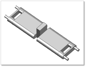
Figure 27.43 Inner pin track link (Track link (I)) geometric entity
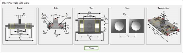
Figure 27.44 Inner pin track link (Track link (I)) dimension information
Ll |
Link Body Left Length |
Lr |
Link Body Right Length |
Hu |
Link Body Upper Height |
Hb |
Link Body Lower Height |
Lp |
Pin Length |
Wb |
Link Body Width |
Wcnti |
Link Body Contact Inner Width |
Wcnto |
Link Body Contact Outer Width |
Rlp |
Left Pin Position |
Rrp |
Right Pin Position |
Rp |
Pin Radius |
Rc |
Centerguide Position |
Lc |
Centerguide Length |
Tc |
Centerguide Thickness |
Le |
End Connector Length |
Plcnt |
Left Contact Cylinder Position |
Prcnt |
Right Contact Cylinder Position |
Rcnt |
Contact Radius |
Rs |
Shoe Radius |
27.2.6.1. Modeling Options
The user can create a sprocket as follows.
Point, WithDialog
Point: Selects a point on Ground to define the track link. It doesn’t matter where the track link is because the created body is a clone body for segment assembly.
WithDialog: Modifies the property for the track link. The track link is created with clicking OK.
27.2.6.2. Properties
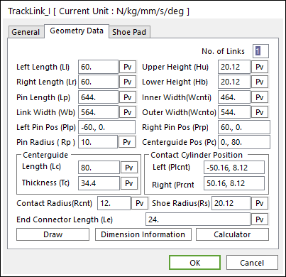
Figure 27.45 Inner Pin Track Link property page [Geometry Data page]
Left Length (Ll): Enters the left length of link.
Right Length (Lr): Enters the right length of link.
Upper Height (Hu): Enters the upper height of link.
Lower Height (Hb): Enters the lower height of link.
Pin Length (Lp): Enters the length of pin body.
Link Width (Wb): Enters the total width of link.
Inner Width(Wcnti): Enters the width of liner link body.
Outer Width(Wcnto): Enters the width of outer link body.
Left Pin Pos (Plp): Enters the position of left pin body.
Right Pin Pos (Rrp): Enters the position of right pin body.
Pin Radius (Rp): Enters the radius of pin body.
Centerguide Pos (Pc): Enters the position of center guide body.
Genterguide
Length (Lc): Enters the length of center guide body.
Thickness (Tc): Enters the thickness of center guide body.
Contact Cylinder Position
Left (Plcnt)
Right (Prcnt)
Contact Radius(Rcnt)
Shoe Radius(Rs)
End Connector Length (Le)
Draw: Shows the shoe pad geometry. The user can change the position and size. Also, the shoe pad geometry can be modified in Shoe Pad page.
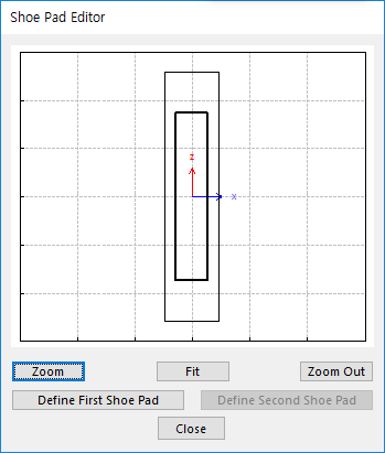
Figure 27.46 Shoe Pad Editor dialog box
Define First Shoe Pad: The user can create a shoe pad by a mouse in Draw dialog box. It can be available in the link.
Define Second Shoe Pad: If Double Shoe Pad in Shoe Pad page is used, this function is activated. The user can create a shoe pad by a mouse in Draw dialog box. It can be available in the link.
Dimension Information: Shows dimension information of the geometry for Roller Link.
Calculator: It is useful for finding specific value to define the relation of between sprockets and Track links. Refer to Calculator.