9.1.1. General Element
These are structural elements.
They represent a structural characteristic using element properties and nodes.
Elements are connected to the nodes in the sequence and orientation for each element type.
This connectivity is defined automatically by the input file information.
Beam2 Element
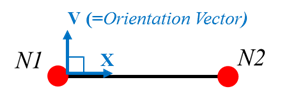
Figure 9.2 Beam2 element
Beam2 is a general beam element with the following capabilities:
Tension
Compression
Torsion
Bending
The element has six degrees of freedom at each node:
Translations in the nodal x, y, and z directions
Rotations in the nodal x, y, and z axes
The element is defined by:
Two nodes
The cross-sectional area
Two area moments of inertia
V vector (Orientation vector)
Element X direction vector is defined a displacement vector from N1 to N2 like figure 1. The Orientation vector V is an perpendicular vector with the element X direction vector.
In the case of FFlex/Beam2 element, the V vector is defined as an Element Y direction vector.
In the case of toolkit Beam element (BeamBelt and R2R Beam), the V vector is defined as an Element Z direction vector.
Shell3 Element
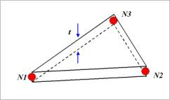
Figure 9.3 Shell3 element
Shell3 is a triangular shell element with the following capabilities.
Bending
Membrane
The element has six degrees of freedom at each node:
Translations in the nodal x, y, and z directions
Rotations in the nodal x, y, and z axes
The element is defined by:
Three nodes
A thickness
Shell4 Element
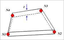
Figure 9.4 Shell4 element
Shell4 is a quadrilateral shell element with the following capabilities:
Bending
Membrane
The element has six degrees of freedom at each node:
Translations in the nodal x, y, and z directions
Rotations in the nodal x, y, and z axes
The element is defined by:
Four nodes
Thickness
Shell9 Element
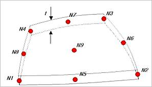
Figure 9.5 Shell9 element
Shell9 is a high order quadrilateral shell element with the following capabilities:
Bending
Membrane
The element has six degrees of freedom at each node:
Translations in the nodal x, y, and z directions
Rotations in the nodal x, y, and z axes
The element is defined by:
Four corner nodes
Four edge nodes
One center nodes
Thickness
Solid4 Element
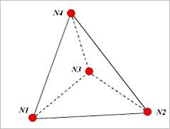
Figure 9.6 Solid4 element
Solid4 is used for the 3-D modeling of solid structure. The element has three degree of freedom at each node (translations in the nodal x, y and z directions). The element is defined by 4 geometric corner nodes.
Solid5 Element
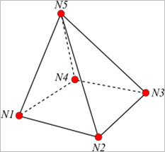
Figure 9.7 Solid5 element
Solid5 is used for the 3-D modeling of solid structure. The element has three degree of freedom at each node (translations in the nodal x, y and z directions). The element is defined by 5 geometric corner nodes.
Solid6 Element
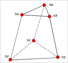
Figure 9.8 Solid6 element
Solid6 is used for the 3-D modeling of a solid structure. The element has three degree of freedom at each node (translations in the nodal x, y and z directions). The element is defined by 6 geometric corner nodes.
Solid8 Element
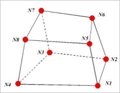
Figure 9.9 Solid8 element
Solid8 is used for the 3-D modeling of a solid structure. The element has three degree of freedom at each node (translations in the nodal x, y and z directions). The element is defined by 8 geometric corner nodes.
Solid10 Element
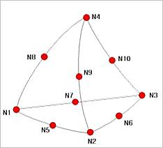
Figure 9.10 Solid10 element
Solid10 is used for the 3-D modeling of solid structure. The element has three degree of freedom at each node (translations in the nodal x, y and z directions). The element is defined by:
4 corner nodes
6 edge nodes
Solid26 Element
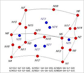
Figure 9.11 Solid26 element
Solid26 is used for the 3-D modeling of solid structure. The element has three degree of freedom at each node (translations in the nodal x, y and z directions). The element is defined by:
8 corner nodes
12 edge nodes
6 face nodes