2.2.7. Working Plane Toolbar
This supports functions to control the working plane of the Working Window.
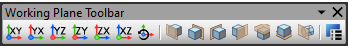
Figure 2.60 Working Plane Toolbar
Working Plane Change
Change to XY: Change the Working Plane to the XY plane. Shortcut is the Shift+X key.
Change to YX: Change the Working Plane to the YX plane. Shortcut is the Shift+S key.
Change to YZ: Change the Working Plane to the YZ plane. Shortcut is the Shift+Y key.
Change to ZY: Change the Working Plane to the YZ plane. Shortcut is the Shift+D key.
Change to ZX: Change the Working Plane to the YZ plane. Shortcut is the Shift+Z key.
Change to XZ: Change the Working Plane to the XZ plane. Shortcut is the Shift+A key.
Rotate Working Plane: The working plane is rotated by 90 degrees, each time the user clicks this icon.
Change to Front: Change the Working Plane to the front of model. Shortcut is the Shift+F key.
Change to Back: Change the Working Plane to the back of model. Shortcut is the Shift+R key.
Chang to Left: Change the Working Plane to the left of model. Shortcut is the Shift+V key.
Chang to Right: Change the Working Plane to the right of model. Shortcut is the Shift+G key.
Chang to Top: Change the Working Plane to the top of model. Shortcut is the Shift+T key.
Change to Bottom: Change the Working Plane to the bottom of model. Shortcut is the Shift+B key.
Change to Plane: Change the Working Plane to the plane selected by user. Shortcut is the W key.
Working Plane Setup
The user can define the reference plane for the Working Plane and modifies the property of the grid.
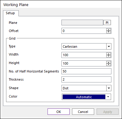
Figure 2.61 Working Plane dialog box
Plane: Selects the plane to work using the navigation command. The user can navigate a face of solid or a plane of marker.
Offset: Defines offset value of the selected plane.
Grid
Type: Selects Cartesian or Cylindrical.
Width: Defines the horizontal distance between grids in the selected plane.
Height: Defines the vertical distance between grids in the selected plane.
No. of Half Horizontal Segments
Thickness: Defines the thickness of a grid in the selected plane.
Shape: Selects Dot or Line or Cross for the working plane shape.
Color: Specifies the working plane color from the selected plane.
Step to define Working Plane
Click the Working Plane Setup icons in the View Control Toolbar
Click PI.
Select a plane as Working Plane as shown below. You can specify a Working Plane in a marker or flat face.
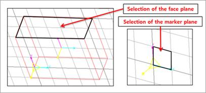
Figure 2.62 Selection of Working Plane
Select Working Plane
Click OK.