10.14. Durability Interface
After simulation, this function helps you to export the required data to FE durability program for Durability analysis. RAN and RPLT files should be generated to use this function.
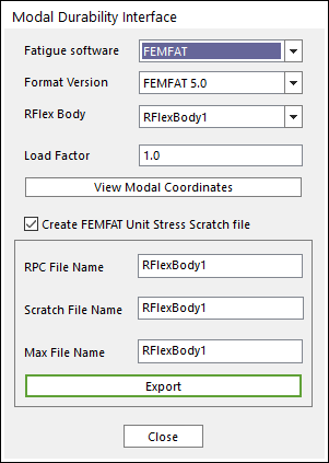
Figure 10.121 Modal Durability Interface dialog box
Fatigue software: Displays the supported fatigue software. RecurDyn supports only FEMFAT Interface for Fatigue Software.
Format Version: Select a FEMFAT version. The Scratch File Format is different for each version.
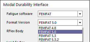
Figure 10.122 Supporting Format Version list
FEMFAT 4.8: Until 4.8 version, use this format.
FEMFAT 5.0: From 4.8 to 5.0 version, use this format.
FEMFAT 5.3: From 5.0 to 5.3 version, use this format.
FEMFAT 5.3.2: From 5.3.2 version, use this format.
RFLEX Body: Selects a RFlex body in the model.
Load Factor: Defines the Scale factor for modal coordinate.
View Modal Coordinates: Shows the used mode list.
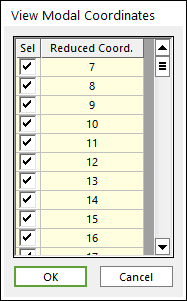
Figure 10.123 View Modal Coordinate dialog box
Create FEMFAT Unit Stress Scratch file: If this option is checked, the user can create Scratch files which contains Unit Stress shape information.
RPC File Name: Defines the name of a file that contains Modal coordinate history data.
Scratch File Name: Defines the name of files that contain Unit Stress shape per each used mode. There are two extensions *.fms and *.fss for the Scratch File. The *.fms file is created for Version 5.3 and lower. The *.fss file is created for Version 5.3.2 and higher.
Max File Name: Defines the name of a file that synchronizes RPC file and Scratch files. If the user inputs this file in FEMFAT, the stress information is listed up automatically as following figure.
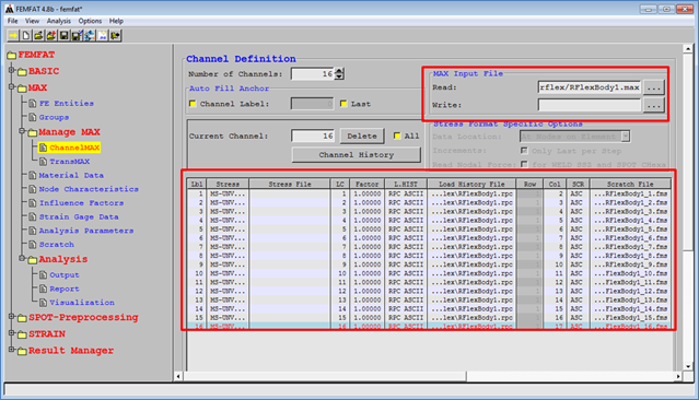
Figure 10.124 FEMFAT using a Max file
Note
If the RFI in which the mid-nodes are removed are used, the user cannot use the Durability Interface for FEMFAT.