28.2.8.2. Example for Generating a Flexible Link
The user can create a flexible link from the converted link body. There are two methods to create a flexible link. One is using RecurDyn/Mesher, the other is importing a mesh data with the FFlex swapping function.
Convert some general link bodies on the track assembly.
Create mesh data for a flexible link.
Import the mesh data. (Swapping the general link bodies for the flexible link)
Define a contact between the flexible link body and the other entities in the Track LM toolkit.
28.2.8.2.1. Defining geometry reference frame for the link in Track (LM) toolkit
Figure 28.59 shows the location and the orientation of the geometry reference frame in the default link shape for Track (LM) toolkit. The location of the geometry reference frame is the middle center point on the below plane of two box-shaped geometries which is for supporting the pin. In the plane the pin supporting boxes and grouser geometries are connected.
Each link position is defined by the geometry reference frame in the track assembly. Therefore, all position and orientation data of the mesh data for generating the flexible link must be defined with respect to the geometry reference frame.
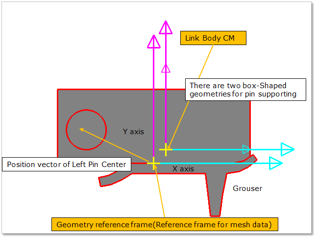
Figure 28.59 Geometry reference frame of the track link body in the Track (LM) toolkit
28.2.8.2.2. Making a mesh data
There are two methods for making a mesh data.
Using RecurDyn/Mesher
Converts link bodies to general bodies using the Link Converter. Refer to Link Convertor.
Makes a mesh data for the converted general link body. The RecurDyn/Mesher can make a mesh data with respect to the geometry reference frame of a link body. For more information, refer to Mesher.
Exports the mesh data to make the other flexible link bodies. For more information, refer to Export Mesh Data.
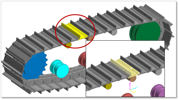
Swaps the general link body for a flexible link body using the Import function in FFlex. The importing procedure is shown in the next page. Refer to Swapping the general link body to a flexible link body.
Using an external mesh program
Converts link bodies to general bodies using the Link Converter. Refer to Link Convertor.
Enters the body edit mode of the converted general link body. Then, export a geometry data file.
Makes a mesh data in an external mesh program. Export the mesh data which is as Nastran format (BDF, DAT file) or Ansys format (CDB file).
Swaps the general link body for a flexible link body using the Import function in FFlex. The importing procedure is shown in the next page. Refer to Swapping the general link body to a flexible link body.
28.2.8.2.3. Swapping the general link body to a flexible link body
The user can swap the general link body made by the link converter function to a flexible link body using the Import function of FFlex function. The changing procedure is as follows.
Click the Import icon of the FFlex group in the Flexible tab.
Change the modeling option from Point to Body.
Click a target body which must be the general link body made by the link converter function.
Select a mesh data file. The mesh data must be a Nastran format (BDF/DAT) or an Ansys format (CDB) file.
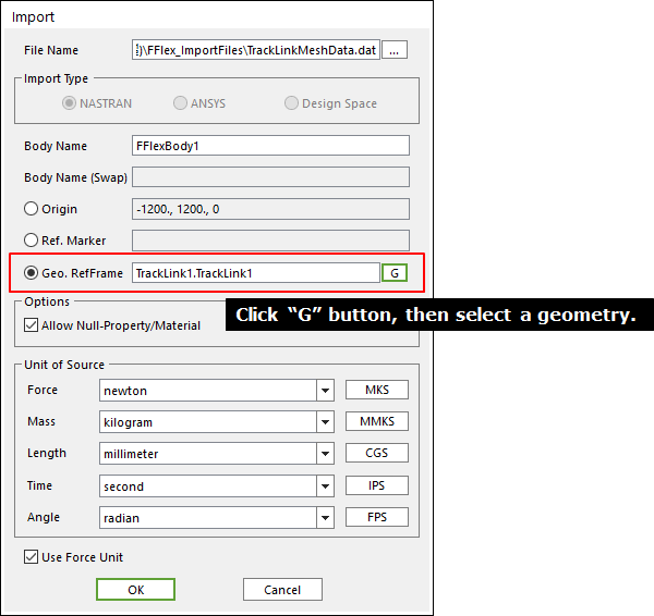
Set the geometry reference frame of dialog box for importing the FFlex body. Figure 28.60 shows the setting method of geometry reference frame. In this case the user should select the third item named Geo. RefFrame in the selection of reference frame. Then the user clicks G and selects the target body or sets the name of the target geometry. Then click OK in the dialog box.
28.2.8.2.4. Defining Contact
If the user wants to perform modeling simply, it is easy to create a contact between a flexible link body and entities (Track (LM)) with the Geo Contact.
The action body of the Geo Contact must be the flexible link body.
When the user defines contact surface for all geometries, for solving speed up, it is better defining each contact case by case.
Contact cases between a sprocket and a track link. Refer to Contact between a Sprocket and Track Links.
The track link pin – the teeth surface of a sprocket. (Major contact case)
The inner surface of a track link – the teeth side of a sprocket.
Single flange. Refer to Contact between a Single Flange and Track Links.
The top surface of a track link – the wheel surface of single flange. (Major contact case)
The outer surface of a track link – the flange of single flange.
Double flange. Refer to Contact between a Double Flange and Track Links.
The top surface of a track link – the wheel surface of a double flange. (Major contact case)
The outer surface of a track link – the outer flange of a double flange.
The inner surface of a track link – the inner flange of a double flange.
Center flange. Refer to Contact between a Center Flange and Track Links.
The top surface of a track link – the wheel surface of a center flange. (Major contact case)
The inner surface of a track link – the inner flange of center flange.
Flat type flange. Refer to Contact between a Flat Type Flange and Track Links.
The top surface of a track link – the wheel surface of a flat type flange.
Guard. Refer to Contact between a Roller Guard and Track Links.
The side surface of a track link pin – the inner surface of a roller guard.
Ground
The surface of road data (or ground surface) - the outer surface of a track link grouser.
28.2.8.2.5. Troubleshooting for the flexible link body
Contact problems
If a contact between a track link assembly and the other Track (LM) entity (a flange or a sprocket) does not work.
Contact search algorithm of a flange or a sprocket changes from the partial search to the full search.
When the user wants to use the Geo Contact
The action body of the Geo Contact must be the converted link body or the flexible link body.
When the small step-size error occurred using a flexible link body.
When a bushing force connected to the flexible link body is too big, the small step-size error occurs. Usually, the pin gap of a link assembly is not zero. It means the bushing force has an initial force. (The difference of between the action and base marker generates a force and a torque.)
Assembly links.
The distance between the pin and the hole in the adjacent two links named Pin gap must have a small value. The pin gap directly influences to the distance of between the action and base markers to the bushing force. Figure1 shows the pin gap when the user makes a track link assembly.
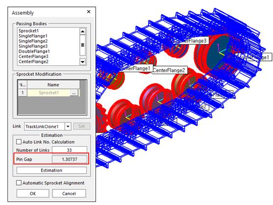
Figure 28.62 Pin gap
When selecting a target link which is converted to a flexible body, select a link has a small pin-gap between the target link and the adjacent link. Figure 28.63 shows that a link of located in the circumference of a sprocket (or a flange) has a big pin-gap than the others.
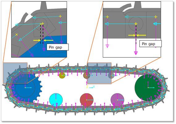
Figure 28.63 Selecting a target body to changing a flexible body
Modify bushing parameters
Changes the stiffness of the bushing force connecting with a flexible body to a smaller value than the pin bushing.
Note
This method influences that the pin-gap between the flexible link and an adjacent link is increased as the simulation progressed.
Re-define the action and base markers of the bushing force
Re-defines the action and the base marker of the bushing force connecting with the flexible link body to the same location.