34.1.3.4. Swing Arm Layout - ArmShaft Type
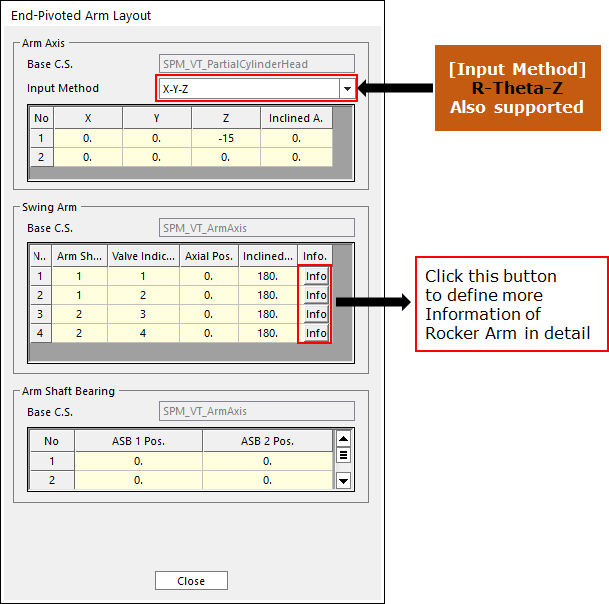
Click Swing Arm Layout in the Valve Global Data dialog box. And then the user can see the following dialog box.
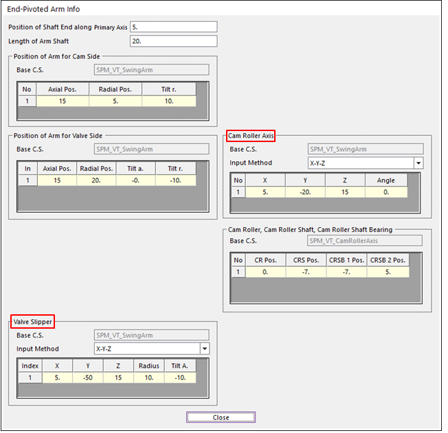
Click Info in the Swing Arm Layout dialog box. And then the user can see the following dialog box.
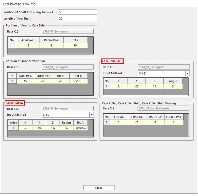
Swing Arm Info dialog box - (a) Cam Roller – Adjust Screw Type
Swing Arm Info dialog box - (b) Cam Roller – Valve Slipper Type
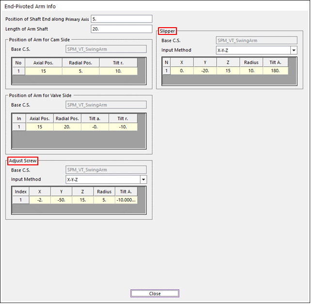
Swing Arm Info dialog box - (c) Slipper – Adjust Screw Type
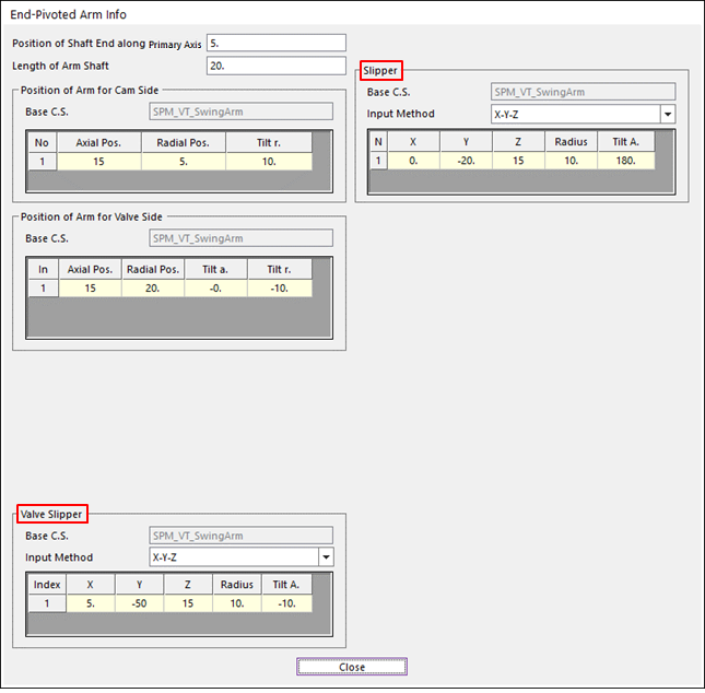
Figure 34.35 Swing Arm Info dialog box - (d) Slipper – Valve Slipper Type
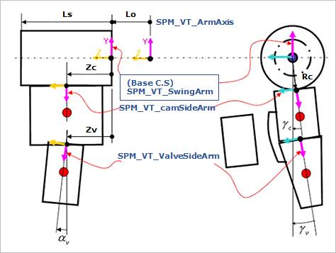
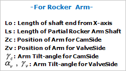
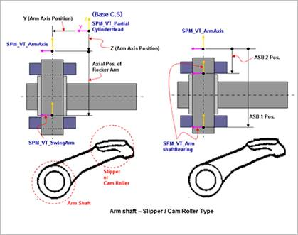
Figure 34.36 Swing Arm Layout 1
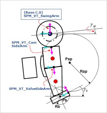
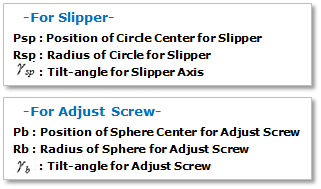
Figure 34.37 Swing Arm Layout 2
After setting up all parameters, click Close in the Swing Arm Layout dialog box.