2.2.2.1.2. CAD Files
ParaSolid File (*.x_t, *.x_b, *.xmt_txt, *.xmt_bin): The user can import a Filename.x_t and a Filename.x_b. These files can be exported as x_t and x_b in the program based in Parasolid kernel. The x_t file has the text file format and the x_b file has the binary file format.
Step(AP203E1, AP214) File(*.step, *.stp): The user can import a Filename.step or a Filename.stp which is usually generated in CAD programs.
IGES(5.3) File(*.igs): The user can import a geometry model to an IGES file.
Table 2.3 Supported Entities for IGES Supported Entities
100 - Circular Arc (Circle)
102 - Composite Curve(only for line or circular arc)
110 - Line
124 - Transformation Matrix
If you do not have an IGES license, RecurDyn provides the limited IGES translator. It supports the only three IGES entities as100 - Circular Arc (Circle), 102 - Composite Curve(only for line orcircular arc), 110 – Line.
ACIS File(*.sat): The user can import a geometry model to an ACIS file.
Pro/E File(*.prt, *.prt.*, *.asm, *.asm.*): The user can import a geometry model to an Pro/E file.
SolidWorks File(*.sldprt, *.sldasm): The user can import a geometry model to an SolidWorks file.
NX File(*.prt): The user can import a geometry model to an NX file.
CATIA Part File(*.CATPart): The user can import a CATIA file. It does not import in the Non-ASCII folder name.
CATIA Product File(*.CATProduct): The user can import a CATIA file. It does not import in the Non-ASCII folder name.
Table 2.4 Caution for CATIA File No Support
File Names with Non-English Characters
RecurDyn does not support reading or writing CATIA V5 files that are named using non-english characters.
CATIA V5 is based on ISO 646 standard which do not support 8 bit character code.
File Names with Non-ASCII Characters
RecurDyn does not support writing CATIA V5 files that are named using non-ASCII characters
CATIA V5 is based on the ISO 646 standard, which does not support multi-byte character code.
The CATIA V5 file name cannot contain non-ASCII characters but the directory name can contain Unicode characters.
Shell Data File(*.shl): The user can import a Filename.shl which is usually generated in CAD programs.
Surface Tessellation Language ASCII format(*.stl): The user can import a Filename.stl which is usually generated in the CAD programs.
OBJ File(*.obj): The user can import a Filename.obj which is usually generated in the CAD programs.
ADAMS ADM File(*.adm): The user can import a Filename.adm, which is generated in ADAMS.
2.2.2.1.2.1. Import Option Dialog
When importing CAD Files, users can use the import options dialog. The options are different according to the CAD file type.
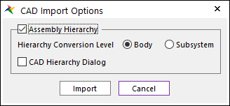
Figure 2.19 CAD Import Options dialog box
These options are common to all the types of CAD files.
Assembly Hierarchy: If the option is not checked, one body has one geometry. If it is checked, one body has some geometries according to the CAD file assembly hierarchy.
Hierarchy Level: The depth of the assembly hierarchy could be more than two. The assembly of geometries is a Body in RecurDyn. The assembly of bodies is a Subsystem in RecurDyn. The assembly of Subsystems is a Subsystem. So, if the hierarchy level is Subsystem, all the assembly hierarchies are processed. If the hierarchy level is Body, more than two depth assemblies are ignored. So, Subsystems are not created.
CAD Hierarchy Dialog: If the option is checked and clicking Import, CAD Hierarchy dialog is open. Users can control the details of the CAD hierarchy.
CAD Import Options
Healing: This option controls the healing of topological data during the translation process. Set this option to true to enable healing. This can be applicable on both the source as well as the target components during the translation. The input file for translation might contain bad data, which means that the translated target file might possibly contain corrupted information. In addition, the geometrical or topological errors might occur during the translation process. To ensure precise and valid translation, connect provides this option for repairing and healing the translated files. Repairing involves checking the translated file for corrupted data and fixing the invalid data. Healing corrects the differences in precision between source and the target entities
Operations Performed: The repairing process can be categorized as follows:
Tolerizing of Target Entities (edges and vertices): Tolerance (precision) of the source entity might be coarser than the target kernel tolerance. This usually results in tolerance-related errors. Edges which perfectly connect at ends in the source system might show gaps in the target, or the vertices that lie on faces may give gap errors. To repair this error, tolerizing is performed on the entities. An appropriate tolerance is computed and applied to every edge and vertex of the body.
Healing of Entities: Healing of entities can be categorized into three types:
Modification of topology of body: This process involves the removal of duplicate and overlapping vertices, removal of small edges, removal of sliver faces from the body, and splitting of edges having large G1 discontinuities in their curves. If the target system is Parasolid, then this involves removal of small edges, and removal of sliver faces from the body.
Modification of geometry of body: This involves reconstruction of self-intersecting and irregular curve geometry of edges, co-edges, and surface geometry of faces, as well as the trimming and sub-setting of underlying surfaces of faces to a uv-box of a face. If the target system is Parasolid, then Translator does not modify the geometry of the body under this option; however, the Deep Healing option does.
Fixing of other invalid data in the body such as loop errors.
Translate Free Curves: This option controls the translation of free curves and wire bodies. Set this option to true to enable the translation of free curve data and wire bodies in the destination format.
Translate Free Surfaces: This option controls the translation of free surface data. Set this option to true to indicate that Translator is to read and translate free surface data.
Translate Solid As Sheets: This option controls whether to export a solid body as a sheet body. Set this option to true to enable translation of a solid body as a sheet body in the destination file format.
Convert Free Point To Marker: This option controls the translation of free point data and convert to the Marker. Set this option to true that the Translator is to read and translate free point data and create the Marker at that position.
Assembly Option (CATIA)
Divide to each Body: This option is the default option in previous versions.
Merge To Single Body: If this option is selected, the multiple imported bodies from one CATPart file or CATProduct file are automatically merged into one body.
Preserve Assembly Structure: If this option is selected, the assembly structure defined in the file is preserved. (only for CATProduct file)
Solid Import Option (STEP)
No Trim and Stitching: This option is the default. If this option is selected, Trim and Stitching option does not work.
Trim and Stitching: If this option is selected, solids are read as trim and stitching is performed.
Options files
optionsACtoPS.txt: options to import ACIS files
optionsCATtoPS.txt: options to import CATIA files
optionsIGtoPS.txt: options to import IGES files
optionsSTEPtoPS.txt: options to import STEP files
optionsPROEtoPS.txt: options to import PRO/E Files
optionsSWtoPS.txt: options to import SolidWorks Files
optionsNXtoPS.txt: options to import NX Files
Default option files are installed in “<Install Dir>\Translator”.
When import or export CAD files, these files are copied in “User\Documents\RecurDyn\<RecurDyn Version>\Translator”.
If you want to modify CAD options, use option files in “User\Documents\RecurDyn\<RecurDyn Version>\Translator”.
Note
When importing Pro/E file, Empty Type Entities can be included. InterOp uses an empty Parasolid body as the owner of various types of groups (representing material properties, axis systems, user defined attributes, etc.). This empty body is also written in a Parasolid file and is used to get attributes. There is no problem to get the empty type entities.
2.2.2.1.2.2. CAD Hierarchy Dialog
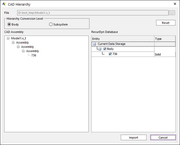
Figure 2.20 Import CAD dialog box
On the left side the CAD assembly hierarchy is shown. On the right side, RecurDyn database is shown. It is converted from the CAD file. User can modify the details of the database.
Modification
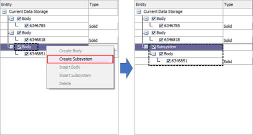
Context Menu: If the right button of the mouse is clicked, the right-click menu is shown. There are Create Body, Create Subsystem, Insert Body, Insert Subsystem, and Delete.
Create Body: A new body is created with selected geometries.
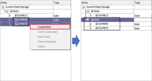
Create Subsystem: A new Subsystem is created with selected bodies.
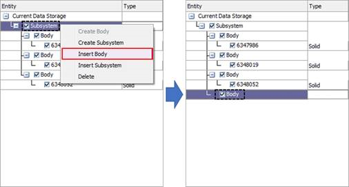
Insert Body: Insert a new empty body to the database.
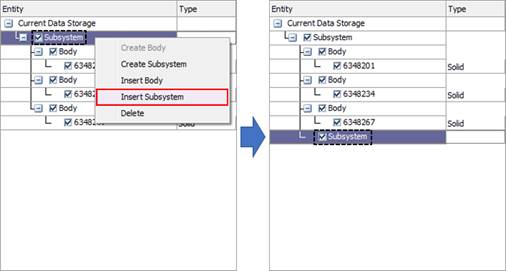
Insert Subsystem: Insert a new empty Subsystem to the database.
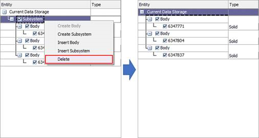
Delete: Subsystem is deleted, and internal Bodies or Geometries goes out to parent subsystem.
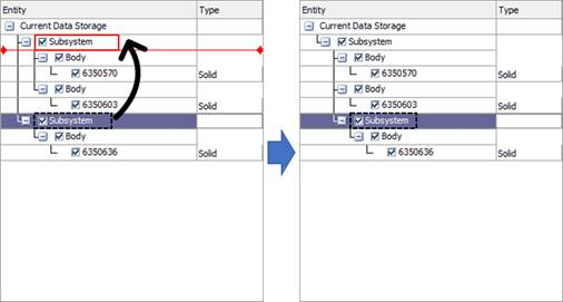
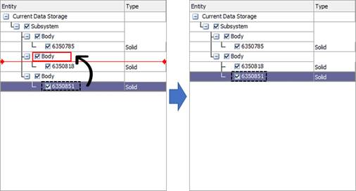
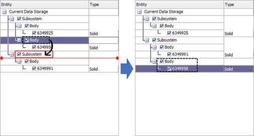
Drag and Drop: Geometries are selected and dragged to other bodies. Bodies and Subsystems work in the same way.
Geometry Node
Body Node
Subsystem Node