30.2.1. Roller
If the shaft center distance is short, proper chain tension can be maintained by adjusting the shaft center distance. If the shaft center distance is long, the slack and fluctuation of chain links can be reduced by installing a roller (idler). A body consisting of three cylinder geometric entities is created. The width and radius of the contact surface of the roller must be large enough for the chain link to pass. The roller is used as adjusting the chain tension. The flange of the roller improves straight drivability.
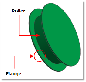
Figure 30.8 Roller geometry
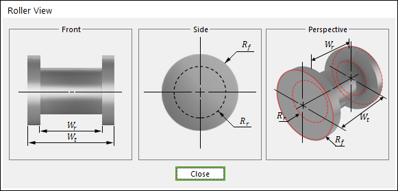
Figure 30.9 Roller dimension information
Wr |
Roller Width |
Wt |
Total Width |
Rf |
Flange Radius |
Rr |
Roller Radius |
30.2.1.1. Modeling Options
The user can create a roller as follows.
Point, Distance
Point: Selects a point to define the center of the roller.
Distance: Defines a distance of the roller.
30.2.1.2. Properties
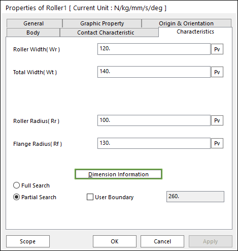
Figure 30.10 Roller property page [Characteristics page]
The Roller property page is shown in Figure 30.10. The parameters are explained below. In order to understand the geometry, refer to Dimension Information.
Roller Width(Wr): Enters the width of roller.
Total Width(Wt): Enters the total width of roller and flange.
Roller Radius(Rr): Enters the radius of roller.
Flange Radius(Rf): Enters the radius of flange.
Full Search: All links are searched for contact.
Partial Search: Some links are searched for contact in some boundary. It is used to reduce total solving time.
User Boundary: In the case of Partial Search, the search boundary can be modified.
Contact between a Roller and a Link
The roller is in contacts with the chain link in the two parts.
The roller center – the plate of chain link
The flange of roller- the side end of chain link pin
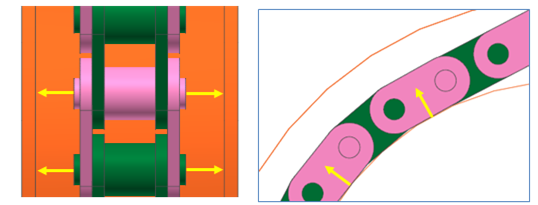
Figure 30.11 Contact between a roller and chain links