6.1.4.1.2. Cylinder
It allows the user to create a solid cylinder that has the information of two points and one radius. By defining the first point and the second point in order to define the center line of the cylinder and specifying the radius on the working window, the user can make it easily. For reference, if the radius is not defined, it is set as 5% of the length of the center line of a cylinder.
6.1.4.1.2.1. Modeling Options
The user can create a cylinder geometry by the following procedure.
Point, Point
Point: Selects a point to define an end surface of the cylinder geometry.
Point: Selects a point to define another end surface of the cylinder geometry. The radius is defined automatically along to the calculated length.
Point, Point, Radius
Point: Selects a point to define an end surface of the cylinder geometry.
Point: Selects a point to define another end surface of the cylinder geometry.
Radius: Defines a radius of the cylinder geometry.
6.1.4.1.2.2. Properties
The user can modify the geometry information using the Cylinder Geometry property page.
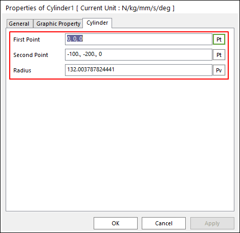
Figure 6.32 Cylinder property page
First Point: Defines a start point for the cylinder body. A geometry reference frame is defined at this point.
Second Point: Defines an endpoint for the cylinder geometry.
Radius: Defines a radius of the cylinder geometry.
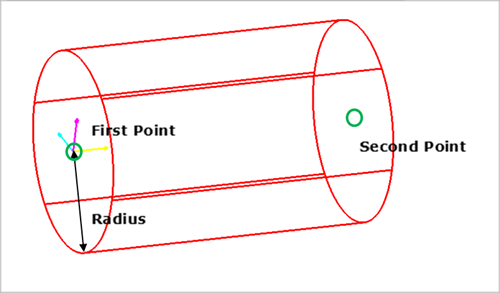
Figure 6.33 Dimensions