10.2.1.2. Generation of Input File
The user gets input files to make an rfi file following steps.
10.2.1.2.1. CMS Analysis (Mechanical APDL)
This section explains how to build FE model and analyze it with CMS method.
The example model is 2D rectangular model. The model can be meshed as shell 63 element with Element edge length option. Shell 63 elements have Real Constant with thickness, 0.05. Steel material is used in this model.
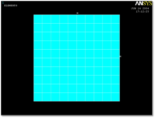
Figure 10.11 Target model
Select Mechanical APDL Product Launcher on the popup menu and specify working directory and job name.
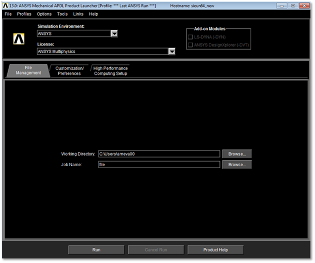
Figure 10.12 ANSYS launcher
Select Structural on the Preferences for GUI filtering
Preferences for GUI filtering
Preferences > Structural
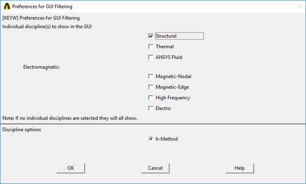
Figure 10.13 Preference for GUI filtering
Select Element Type, Real Constants
Element type
Preprocessor > Element Type > Add/Edit/Delete > Add… > Shell 63 > OK > Close
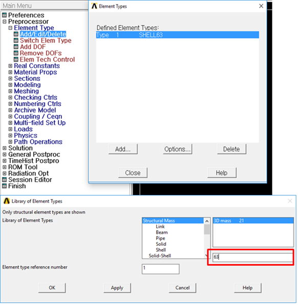
Figure 10.14 Set Element Type
Enter Real Constants
Preprocessor > Real Constants > Add/Edit/Delete > Add > OK
Set shell thicknesses I, J, K, L as 0.05
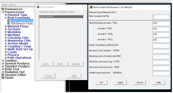
Figure 10.15 Real constant for shell element
Thickness
- Thickness is important parameter for shell element. Ansys do not support Real Constant for some shell element.At the time, thickness can be define using shell section.
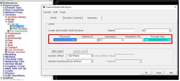
Figure 10.16 Create Sections for Shell Element
Enter Material property
Material property
Preprocessor > Material Props > Material Models > Structural > Linear > Elastic > Isotropic > Specify material number as 1 > OK
Fill in the Young’s modulus(70e9 \(N/m^2\)), Poisson’s ratio(0.33), density(2710 \(kg/m^3\)) > OK
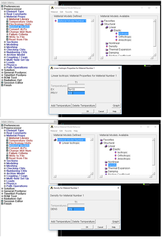
Figure 10.17 Material Property
Create rectangular geometric entity
Create Rectangle by Dimensions
Preprocessor > Modeling > Create > Areas > Rectangle > By Dimensions > OK
Fill the x1, x2, y1, & y2 as 0.0, 0.0, 1.0, & 1.0 > OK
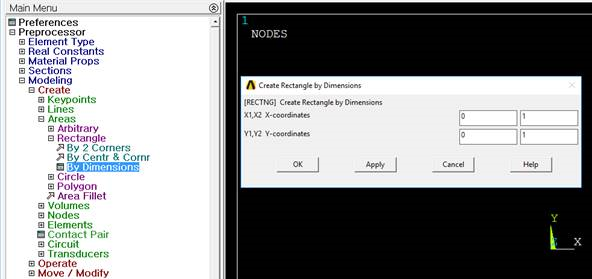
Figure 10.18 Rectangle by Dimensions
Create area meshing using Mesh Tools
Use line set to define element edge length.
Preprocessor > Meshing > MeshTool > Size Controls > Lines > Pick All > OK > SIZE element edge length(0.1) > OK
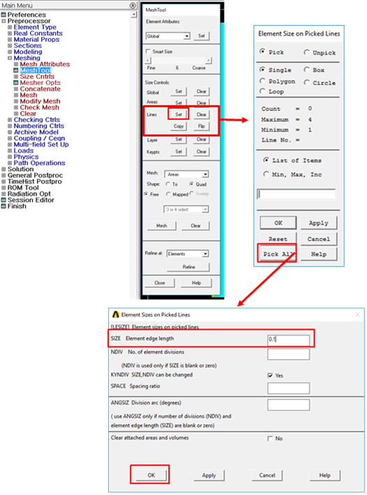
Figure 10.19 Line set with Element edge length
Mesh model
Mesh Tool > Mesh > Select model > OK
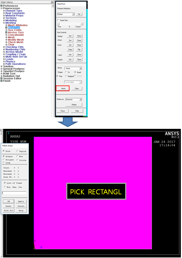
Figure 10.20 Meshed Rectangular geometric entity
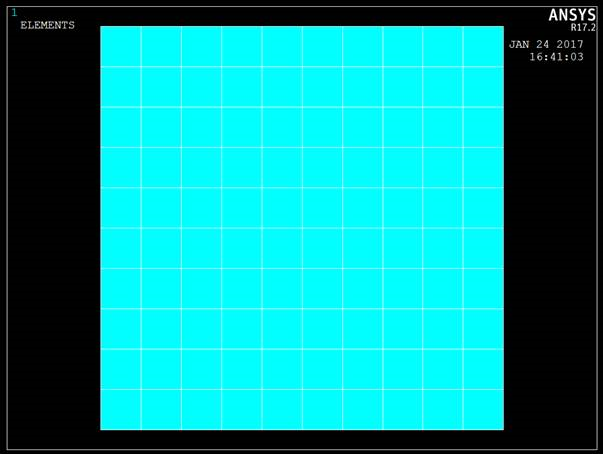
Figure 10.21 Mesh Result
Define Interface nodes
Select> Component Manager
Create Component
Create from ‘Nodes’
Check ‘Pick entities’
Name new component ‘INTERFACE’
Select interface nodes on FE model
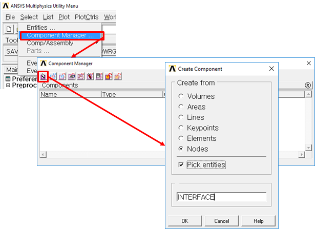
Figure 10.22 Create new component
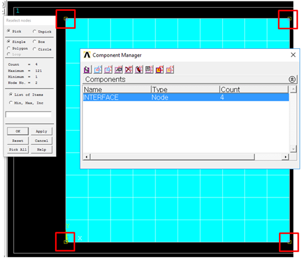
Figure 10.23 Select Interface nodes
Define Parameter
Parameters> Scalar Parameters
Input the number of modes like ‘NMODES=10’
Accept it
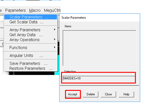
Figure 10.24 Set the number of modes
Read RecurDyn’s input file for CMS analysis
File> Read Input from
Read ‘RecurDyn_AnsysCMS.MAC’
This macro input file is included in the following folder.
‘<Install Dir>\Toolkits\Flexible input files\ANSYS’
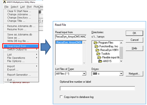
Figure 10.25 Created files
Check the result files.
The four files must exist in work folder.
genCMS.rst
genCMS.mp
genCMS.emat
genCMS.cm
Caution
The user can perform the CMS(Component Mode Synthesis) analysis in ANSYS. CMS allows the user to derive the normal modes and static correction modes at once from ANSYS. It is difficult to perform CMS analysis by the provided steps of ANSYS. So, it is strongly recommended that the user performs CMS analysis with the provided macro file (RecurDyn_AnsysCMS.MAC). This macro file is included in <Install Dir>\Toolkits\Flexible input files\ANSYS\RecurDyn_AnsysCMS.MAC.
If ANSYS does not generate the element matrices file automatically, use the EMATWRITE command. If the user uses the macro file, this command is not needed.
If ANSYS does not generate the file included in material information automatically, the user should type the MPWRITE command in the solution menu. If the user uses the macro file, this command is not needed.
Note
The sample model is supported in <Install Dir>\Toolkits\Flexible input files\ANSYS directory.
10.2.1.2.2. CMS Analysis (Workbench)
This section explains how to build FE model and analyze it with CMS method in Workbench.
The example model is 2D rectangular model.
Select Modal analysis in Analysis Systems.
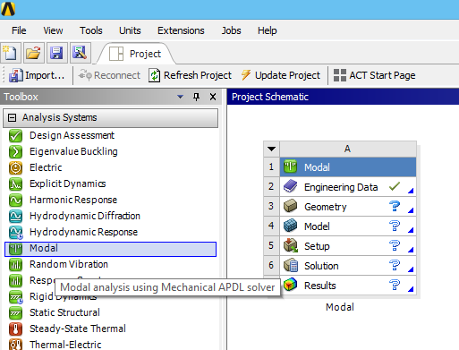
Figure 10.26 Modal analysis system
Create a geometry for FE model.
Enter DesignModeler program in the popup menu on Geometry.
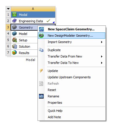
Figure 10.27 Popup Menu on Geometry
Create a rectangle geometry in DesignModeler.
Activate Sketching Toolboxes by clicking Sketching page next to Modeling page. Create a 1m*1m rectangle on XY Plane by using Draw and Dimensions feature.
Create a surface from the sketch by using Surfaces From Sketches.
Generate the geometry by using Generate.
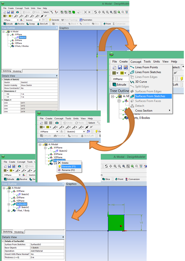
Figure 10.28 DesignModeler
Create a FE model and Analysis.
Enter Edit… on the popup menu on Model.
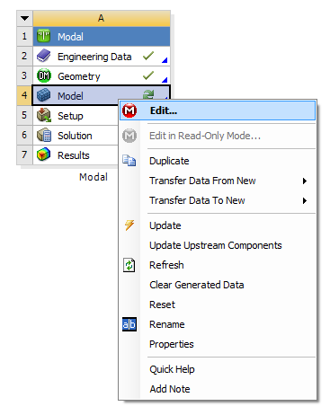
Figure 10.29 Popup Menu on Model
Define the thickness of the surface geometry as 0.05.
Define the material as Structural Steel.
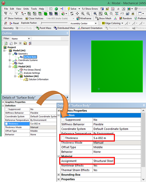
Figure 10.30 Setting the thickness
Mesh the surface geometry.
Set the element size as 0.1 by using Body Sizing.
Set the mesh type as all quad in Automatic Method.
Mesh with Generate Mesh.
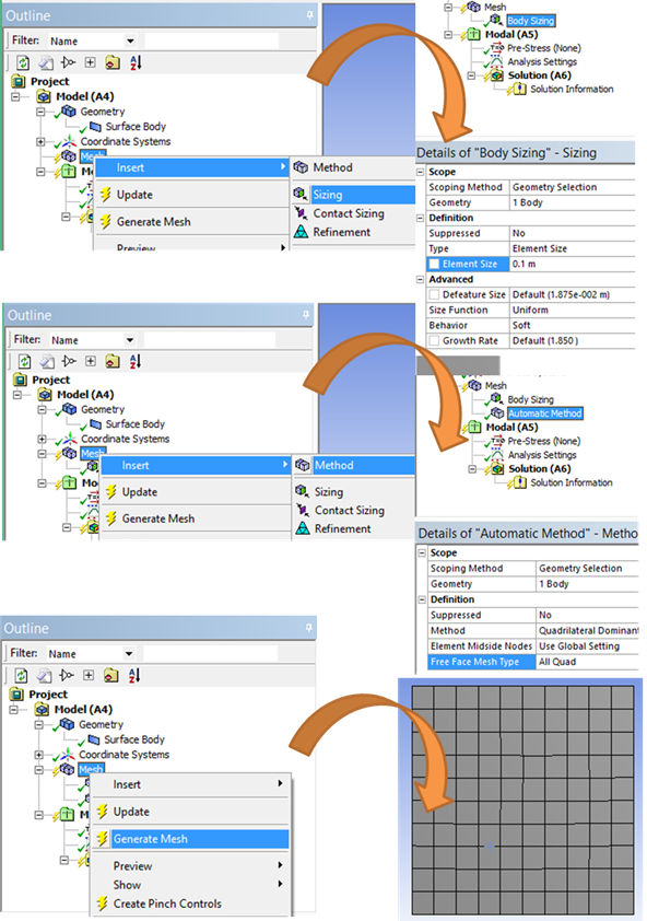
Figure 10.31 Mesh the surface geometry
Define interface nodes.
Create a Remote Point to define interface nodes.
Set four vertices as Geometry
Set X, Y, and Z Coordinate as -0.1, 0.5, and 0.
Set Rigid Behavior in Definition
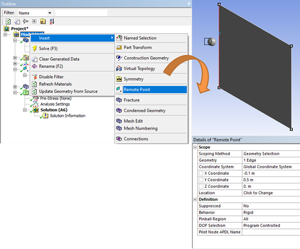
Figure 10.32 Setting Remote Point
Insert a Command to define the name for the remote point.
“MASTER_1=_npilot”
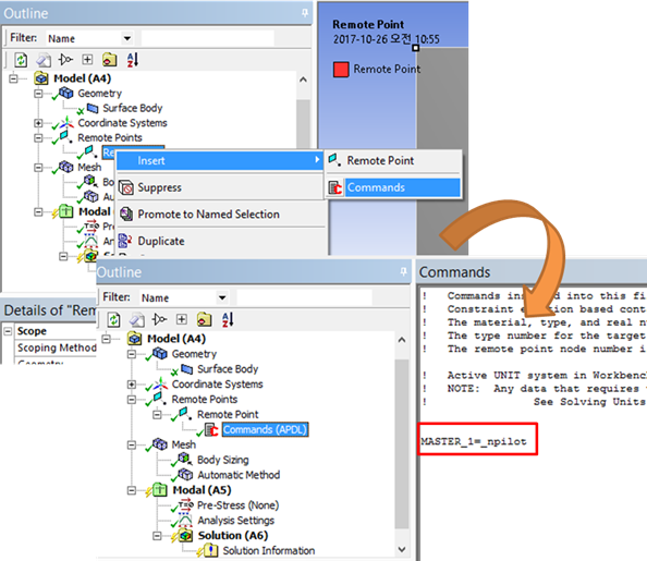
Figure 10.33 Command for Remote Point
Create a Point Mass to define mass element.
Set Scoping Method as Remote Point.
Set Remote Points as the created Remote Point.
Set the mass as 1-e6 in Definition
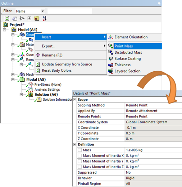
Figure 10.34 Setting Point Mass
Solve Modal Analysis
Define Analysis Settings
In order to include strain shape and stress shape, check Output Controls.
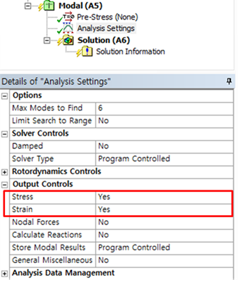
Figure 10.35 Analysis Settings
Solve
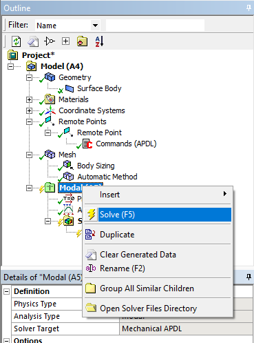
Figure 10.36 Performing Modal Analysis
Select Mechanical APDL in Component Systems
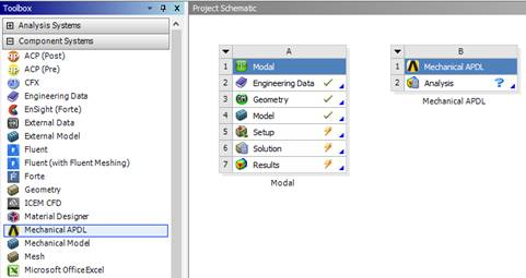
Figure 10.37 Mechanical APDL in WorkBench
Create a MAC file.
Insert a command for CMS analysis.
Edit the macro input file contents provided by RecurDyn. The file is in <Install Dir>\Toolkits\Flexible input files\ANSYS folder.
NMODES and CM parameters should be inputted.
“NMODES=10”
“nsel,s,,,MASTER_1”
“CM,INTERFACE,node”
Save the modified file
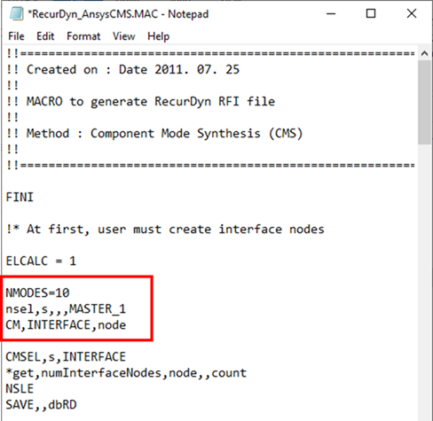
Figure 10.38 Edited MAC file
Solve CMS Analysis.
Assign Model setting
Add created MAC file
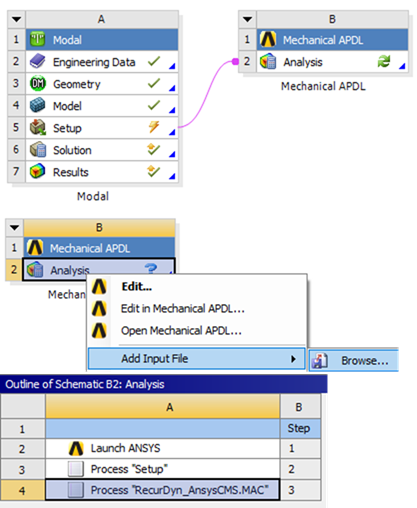
Figure 10.39 CMS Analysis setting
Solve
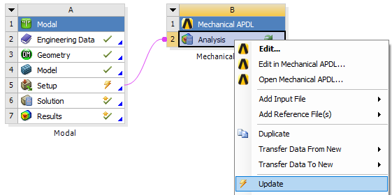
Figure 10.40 Performing CMS Analysis
Check the result files.
The file is in <ProjectFolder>dp0APDLANSYS
The four files must exist in this folder.
genCMS.rst
genCMS.mp
genCMS.emat
genCMS.cm
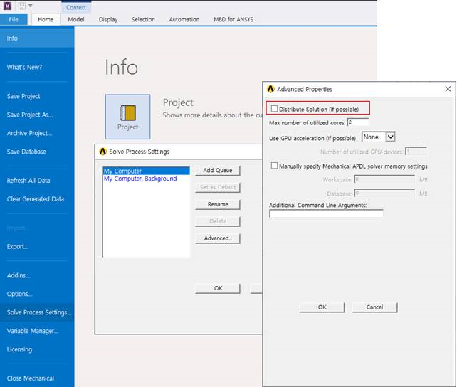
Note
For accurate analysis, Distribute Solution option should be turned off in Mechanical program.
10.2.1.2.3. Modal Analysis (Mechanical APDL)
The example model is 2D rectangular model. The model meshed based on shell 63 element with Element edge length option. Shell 63 element has Real Constant with thickness and the value are same as 0.05 for all. Furthermore, use material property like as steel and boundary condition to fix all degree of freedom impose at all left side node.
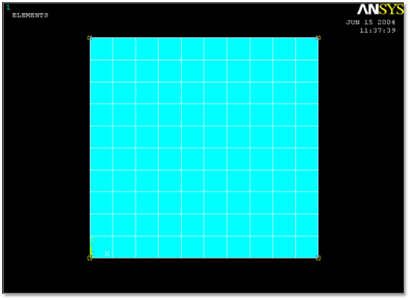
Figure 10.41 Target model
Select Mechanical APDL Product Launcher on the popup menu and specify working directory and job name.
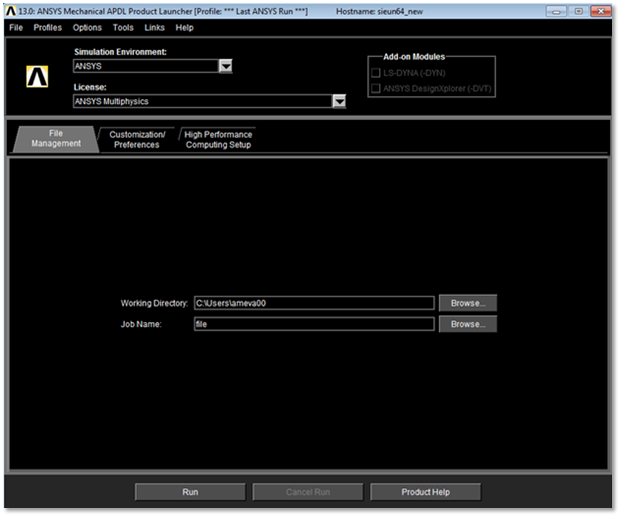
Figure 10.42 Interactive dialog box
Select Structural on the Preferences for GUI filtering
Preferences for GUI filtering
Preferences > Structural
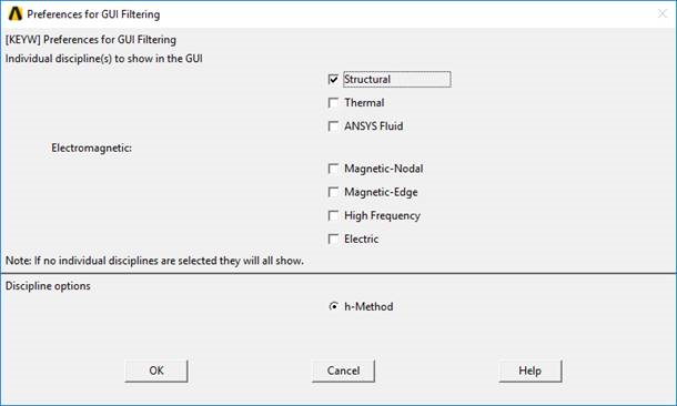
Figure 10.43 Preference for GUI filtering
Select Element Type, Real Constants
Element type
Preprocessor > Element Type > Add/Edit/Delete > Add… > Shell 63 > OK > Close
Enter Real Constants
Preprocessor > Real Constants > Add/Edit/Delete > Add > OK
Set shell thicknesses I, J, K, L as 0.05
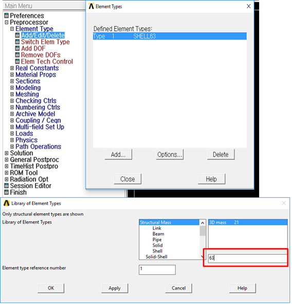
Figure 10.44 Real constant for shell element
Thickness
- Thickness is important parameter for shell element. Ansys do not support Real Constant for some shell element.At the time, thickness can be define using shell section.
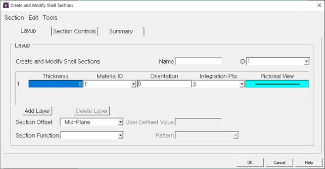
Figure 10.45 Create Sections for Shell Element
Enter Material property
Material property
Preprocessor > Material Props > Material Models > Structural > Linear > Elastic > Isotropic > Specify material number as 1 > OK
Fill in the Young’s modulus(70e9 \(N/m^2\)), Poisson’s ratio(0.33), density(2710 \(kg/m^3\)) > OK
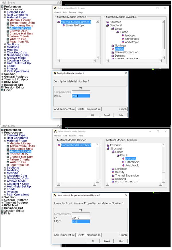
Figure 10.46 Material Property
Create rectangular geometric entity
Create Rectangle by Dimensions
Preprocessor > Modeling > Create > Areas > Rectangle > By Dimensions > OK
Fill the x1, x2, y1, & y2 as 0.0, 0.0, 1.0, & 1.0 > OK
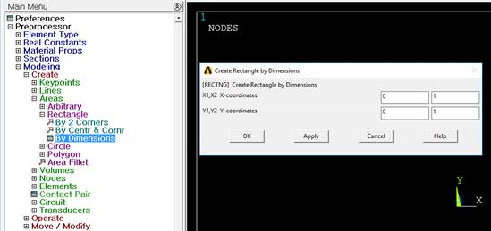
Figure 10.47 Rectangle by Dimensions
Create area meshing using Mesh Tools
Use line set to define element edge length.
Preprocessor > Meshing > MeshTool > Size Controls > Lines > Pick All > OK > SIZE element edge length(0.1) > OK
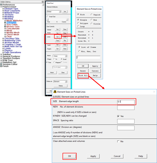
Figure 10.48 Line set with Element edge length
Mesh model
Mesh Tool > Mesh > Select model > OK
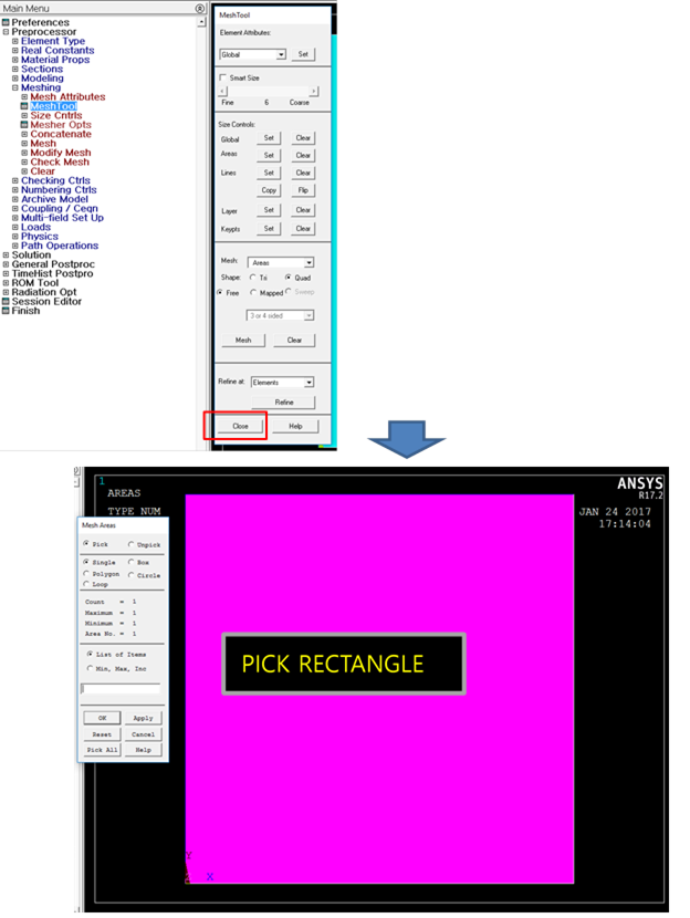
Figure 10.49 Meshed Rectangular geometric entity
Impose Boundary Conditions on nodes
Apply at node
Fix all degree of freedom of left side node
Solution > Loads > Define Loads > Apply > Structural Displacement > On Nodes > Box > drag the window > OK > All DOF > OK
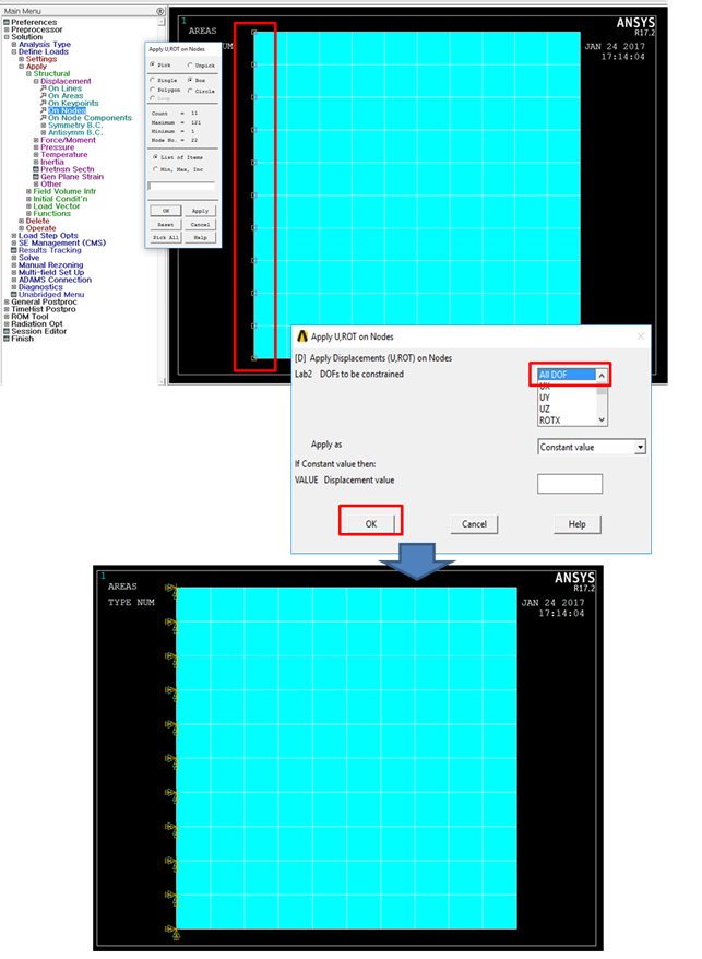
Figure 10.50 Boundary condition
Create output files
Create *.mp file
Ansys Command Prompt > ‘mpwrite’
Create *.emat file
Ansys Command Prompt > ematwrite, yes’
Perform modal analysis
Set Analysis Type
Solution > Analysis Type > New Analysis > Modal
Set Analysis Options
Solution > Analysis Type > Analysis Options
Determine the Number of modes to extract and check lumped mass option
You can also define Start and End frequency
Perform analysis
Solution > Solve > Current LS > Finish
Check created files
Created files were stored in working directory
file.rst
file.mp
file.emat