41.3.2. MFSwift
In addition to the Magic Formula description in the MFTire part of model, the MFSwift uses a rigid ring model in which the tire belt is assumed to behave like a rigid body. This means that the model is accurate in the frequency range where the bending modes of tire belt can be neglected, which, depending on the tire type is up to 60 – 100 Hz. The MFSwift has been validated using measurements of a rolling tire (7 to 40 m/s) containing frequencies up to 120 Hz. The model includes essential gyroscopic effects. The tire model functionality is primarily based on [1] – [6]. TNO has made several crucial changes and enhancements in cooperation with Prof. Pacejka to the models as described in [1] to improve functionality, robustness, calculation times, user-friendliness and compatibility between various operation modes.
MF-Swift uses an efficient single point contact for the slip calculation which results in full compatibility with the MF-Tire. Due to the introduction of a so-called phase leading network for the pneumatic trail, MFSwift is suitable for path curvature with a wavelength in the order of two times the contact length. For braking/traction applications, wavelengths as small as half the contact length are well described. The transient slip behavior is well described up to full sliding, due to modeling of decrease in relaxation length for increased slip levels.
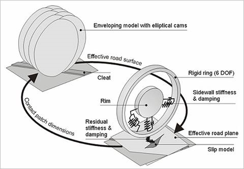
Figure 41.23 Graphical representation of the MF-Swift model
Five main elements of the model structure can be distinguished:
Rigid ring with 6 degrees of freedom
The primary vibration modes of tire belt are described by an elastically suspended rigid ring representing the tire sidewalls and belt with its mass and inertia properties.
Residual stiffness & damping
These have been introduced between contact patch and rigid ring to ensure that the total quasi-static tire stiffnesses in vertical, longitudinal, lateral and yaw directions are modeled correctly. The total tire model compliance is made up of the carcass (ring suspension) compliance, the residual compliance (in reality a part of the total carcass compliance) and the tread compliance.
Contact patch model
This part features horizontal tread element compliance and partial sliding. On the basis of this model, the effects of the finite length and width of the footprint are approximately included.
Generic 3D obstacle enveloping model
This part calculates effective road inputs to enable the simulation of the tire moving over an uneven road surface with the enveloping behavior of the tire properly represented. The actual three-dimensional profile of the road is replaced by a set of four effective inputs the:
Effective height
Effective forward
Camber slopes of the road plane
Effective forward road curvature (that is largely responsible for the variation of the tire effective rolling radius)
Magic Formula steady-state slip model
This part (MF-Tire 6.1) describes the nonlinear slip force and moment properties. This enables an accurate response also for handling maneuvers. To see more to the MF-Swift tire model, please refer to [1] and [6].
Note
The following modules necessitate the MF-SWIFT license.
2D short wavelength road contact, use mode ISWITCH=x4xx.
3D short wavelength road contact, use mode ISWITCH=x5xx.
Rigid ring, use mode ISWITCH=xx3x.
Rigid ring + initial statics, use mode ISWITCH=xx4x.
Combined + turn slip, use mode ISWITCH=xxx5.