19.2.2.2. Stiffness
Stiffness supports output of bearing stiffness information. if animation file is loaded, user can check stiffness information for each beatring in various ways. When the simulation is completed, an output file(extensiton csv) containing bearing stiffness information at each time step is created for each bearing. The file name is made by a combination of the model name and the entity name for bearing.
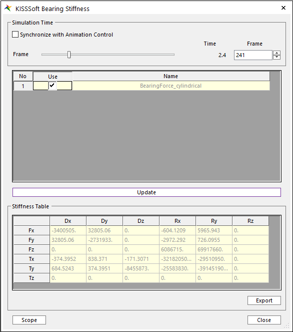
Figure 19.16 Stiffness dialog box
Synchronize with Animation Control: Adjust frame to the current animation time step.
Frame: Define sepcific time step.
Use: Check bearing in order to output stiffness information
Update: Update stiffness information into the stiffness table.
Stiffness Table: Bearing stiffness information is displayed by 6 by 6 matrix form. It is defined with respect to bearing base marker.
Export: Export bearing stiffness result file which contains current simulation time and 6 by 6 bearing stiffness matrix.
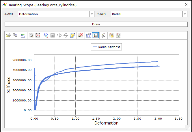
Figure 19.17 Bearing Scope dialog box
Scope: User can check stiffness information in 2D plot format.
X-axis: Select the type of X-axis. Deformation and Time are supported. Deformation is defined mismatch between center axis of outer bearing to center axis of inner bearing.
Y-axis: Select the type of Y-axis. it supports stiffness by radial, axial and tilt displacement.
Radial: It means stiffness in radial direction. If X-axis is deformation, it is defined by radial displacement from center of outer bearing to center of inner bearing.
Axial: It means stiffness by axial direction. If X-axis is deformation, it is defined by relative displacement of inner bearing to outer bearing in axial direction.
Tilt: It means stiffness by axis misalignment. If X-axis is deformation, it is defined by axis misalignment between axis of inner bearing and axis of outer bearing.