36.2.3. Guide
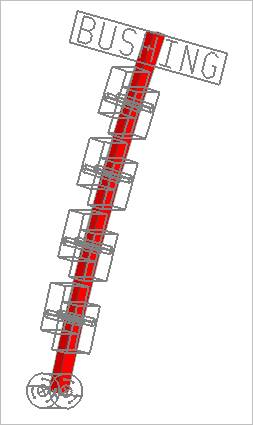
Figure 36.14 Timing Chain Guide
Click Geometry of Guide in the Component Builder dialog box. And then the user can see the dialog box.
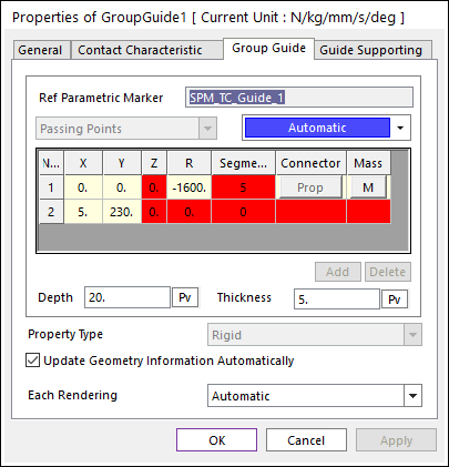
Figure 36.15 Group Guide property page [Group Guide page]
Ref Parametric Marker: Shows the reference parametric marker.
X,Y.Z: Defines a passing point of the guide based on Ground.InertiaMarker.
R: Defines a radius of the guide passing two points
Segments: Defines the number of segments in the guide.
Connector: If Property Type is RSDA or Beam, the use can modify the property by clicking Prop.
Depth: Defines a depth of the guide.
Thickness: Defines a thickness of the guide.
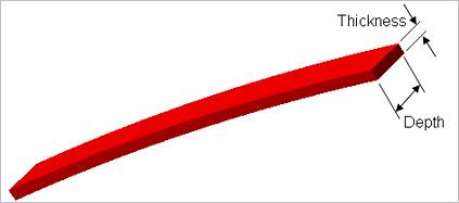
Figure 36.16 Definition of depth and thickness of guide
Property Type: Selects a connecter type between segments. Rigid, RSDA, and Beam type are supported. The user can modify properties of connector by clicking Prop.
Rigid: All guide segments are connected by fixed joints.
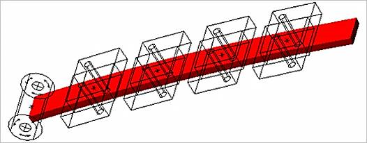
Figure 36.17 Rigid type of Guide
RSDA: All guide segments are connected by the revolute joints and rotational spring damper. For more information, refer to Rotational Spring Force supported as a Force entity.
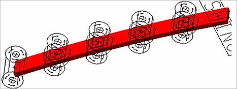
Figure 36.18 RSDA type of Guide
Beam: All guide segments are connected by beam elements. For more information, refer to Beam Force supported as a Force entity.
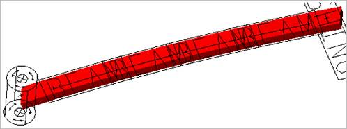
Figure 36.19 Beam type of Guide
Each Rendering: The selected mode can be displayed in Each Render mode.
Guide Supporting
Defines the position and type of connectors between guides and Guide.
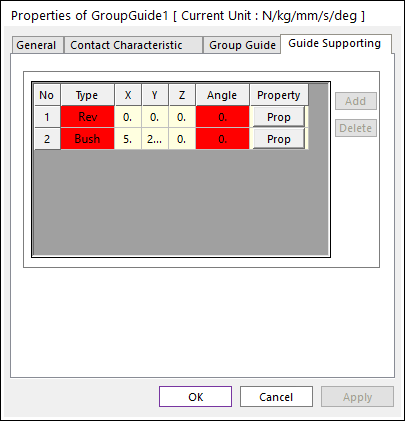
Figure 36.20 Group Guide property page [Guide Supporting page]
Type: Selects a connector type between guides and Ground. Bush, Rev, Contact type are supported.
Bush
Rev
Contact
X,Y,Z
Angle
Property
Add
Delete